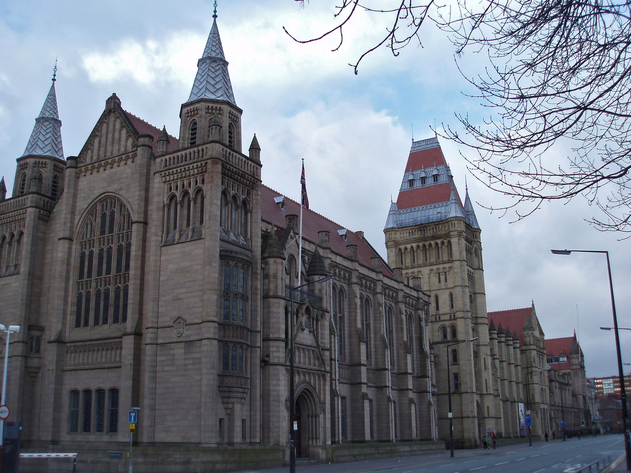
 This project was given to me from the University estates department who were wanting a representation of the University of Manchester’s Whitworth hall and tower that make up the Oxford road side of the old quadrangle complex. The model would then be used in a snow globe for a Digital Christmas Card sent out across the University.
As the project required the model to be waterproof I decided it would be a good opportunity to record the process of using Ureol, commonly known as Chemi-Wood or Model Board.
Whilst in this case I am using Chemi-Wood as the main material, the methods used are applicable to any kind of massing representation – this one having perhaps more detail than normally required due to its purpose.
Here is my step by step record of the process undertaken for around 5 hours over a period of a week when ever I found any time! I have included my rough sketches and thought process description to help understand how I chose to tackle the difference aspects of this representation.
Planning
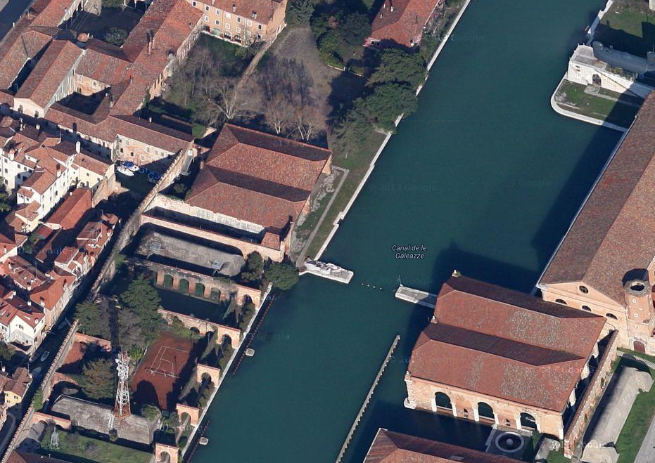
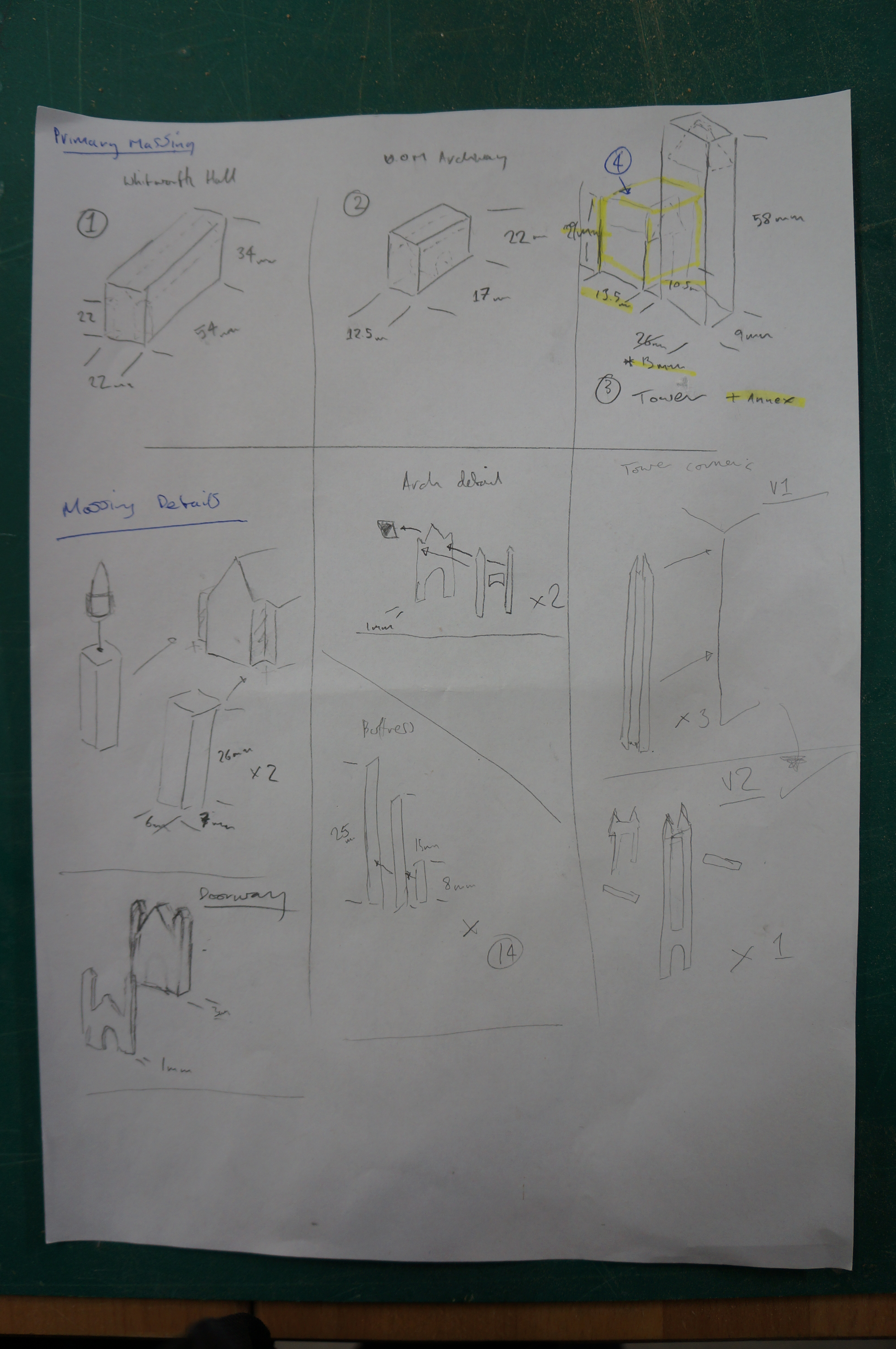
The model had to be a maximum of 100mm long to allow it to fit within a snow globe. Firstly I scaled the CAD Drawings based on the required size and printed a plan and elevation to directly reference the model components as building each one. Having an accurate plan to work to is essential. Always check and double check it is printed to the correct scale.
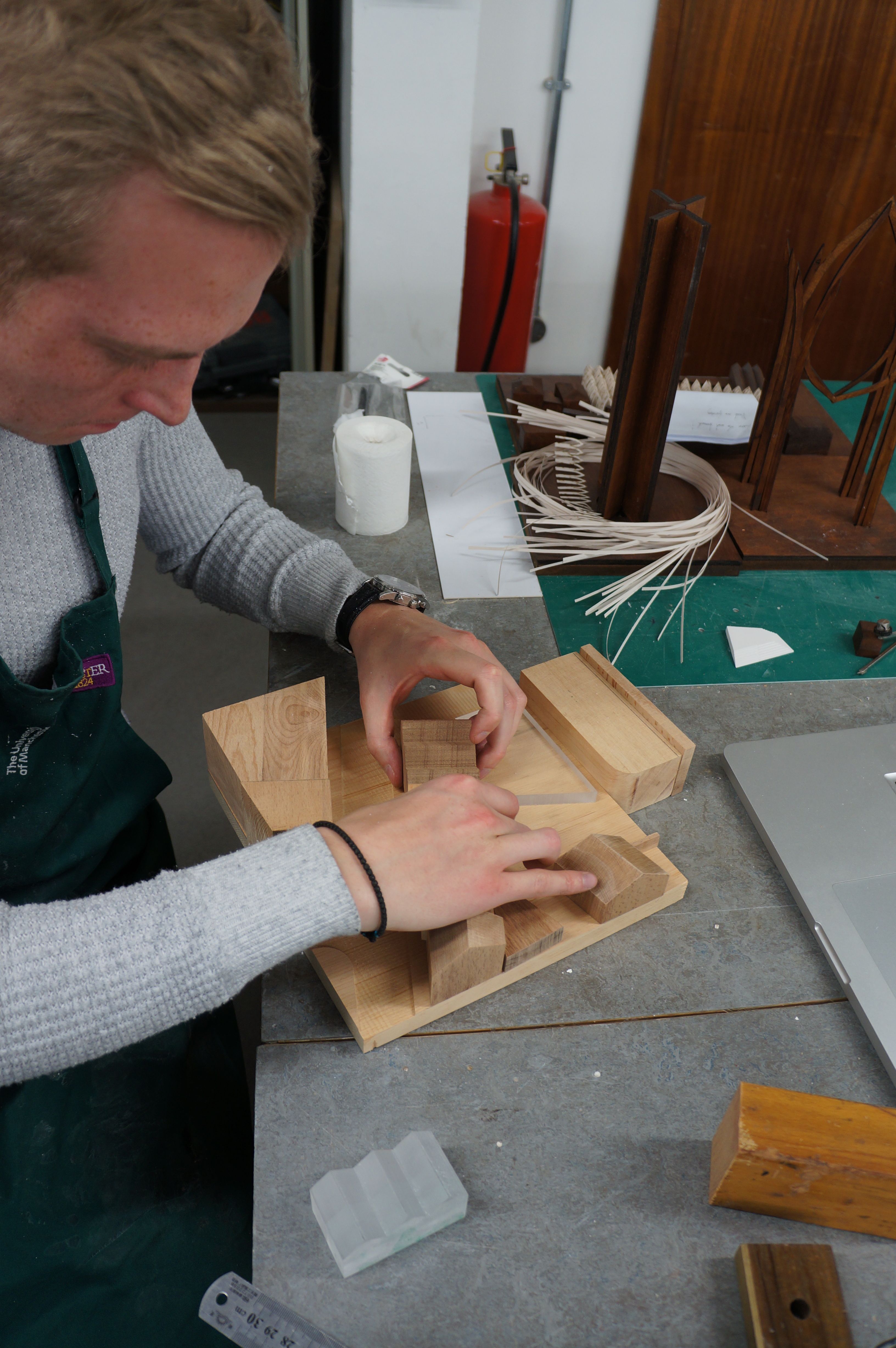
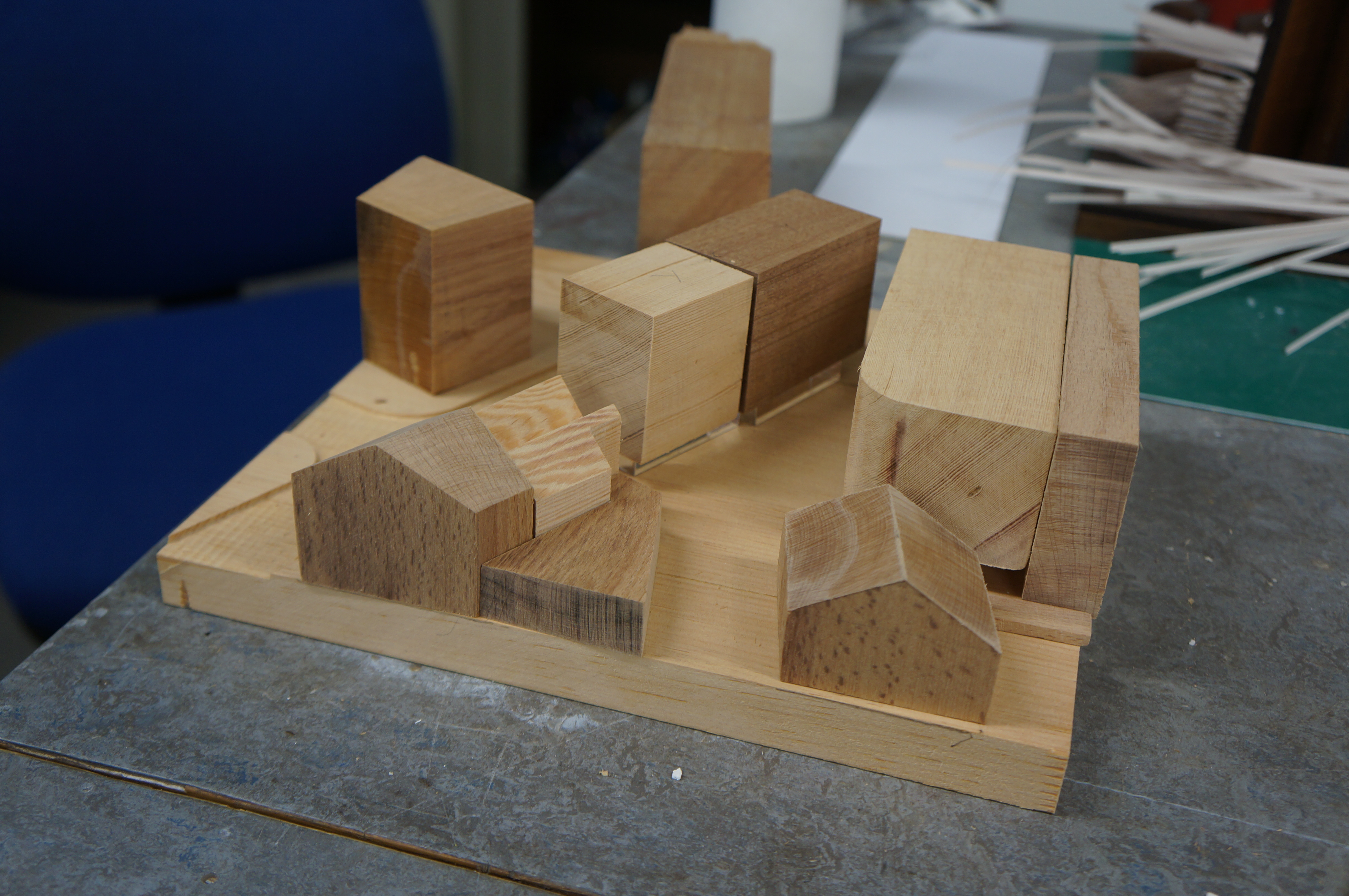
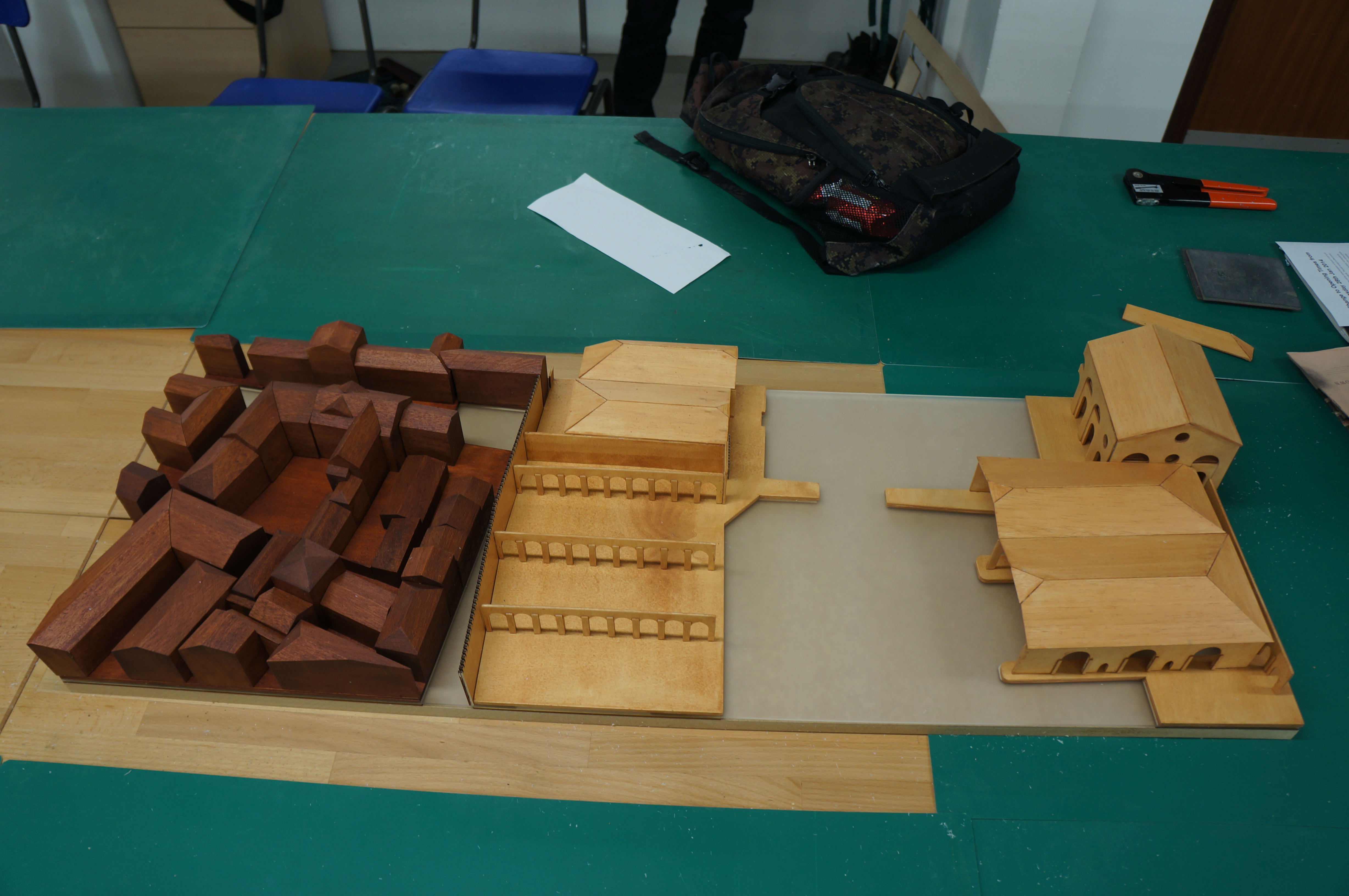
 With the printed plans as a guide I began dividing the model into components to be massed out, thinking in my head and in turn on paper about any pitches or areas that may need to be removed later.
By identifying commonly sized components, or close to the same size you can then best determine how to cut your material to avoid waste. In this case the height and width of two components happened to be the same so I started by cutting a piece at 22mm wide.

Primary Massing
Cutting a block at 22mm width gave me a thin sheet off-cut which will come in handy later. Always keep hold of thin strips like this as they prove very useful when making add on details.
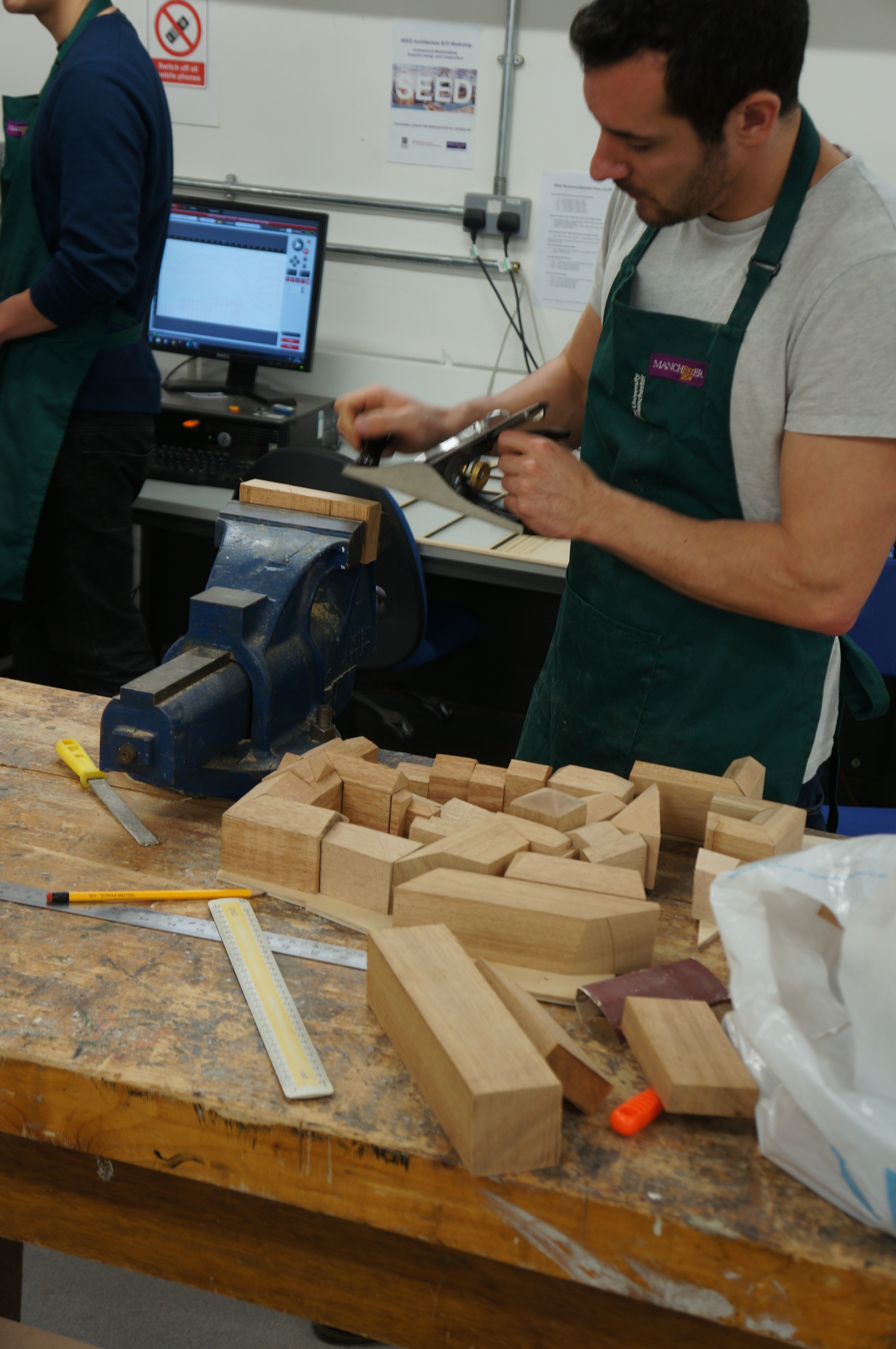
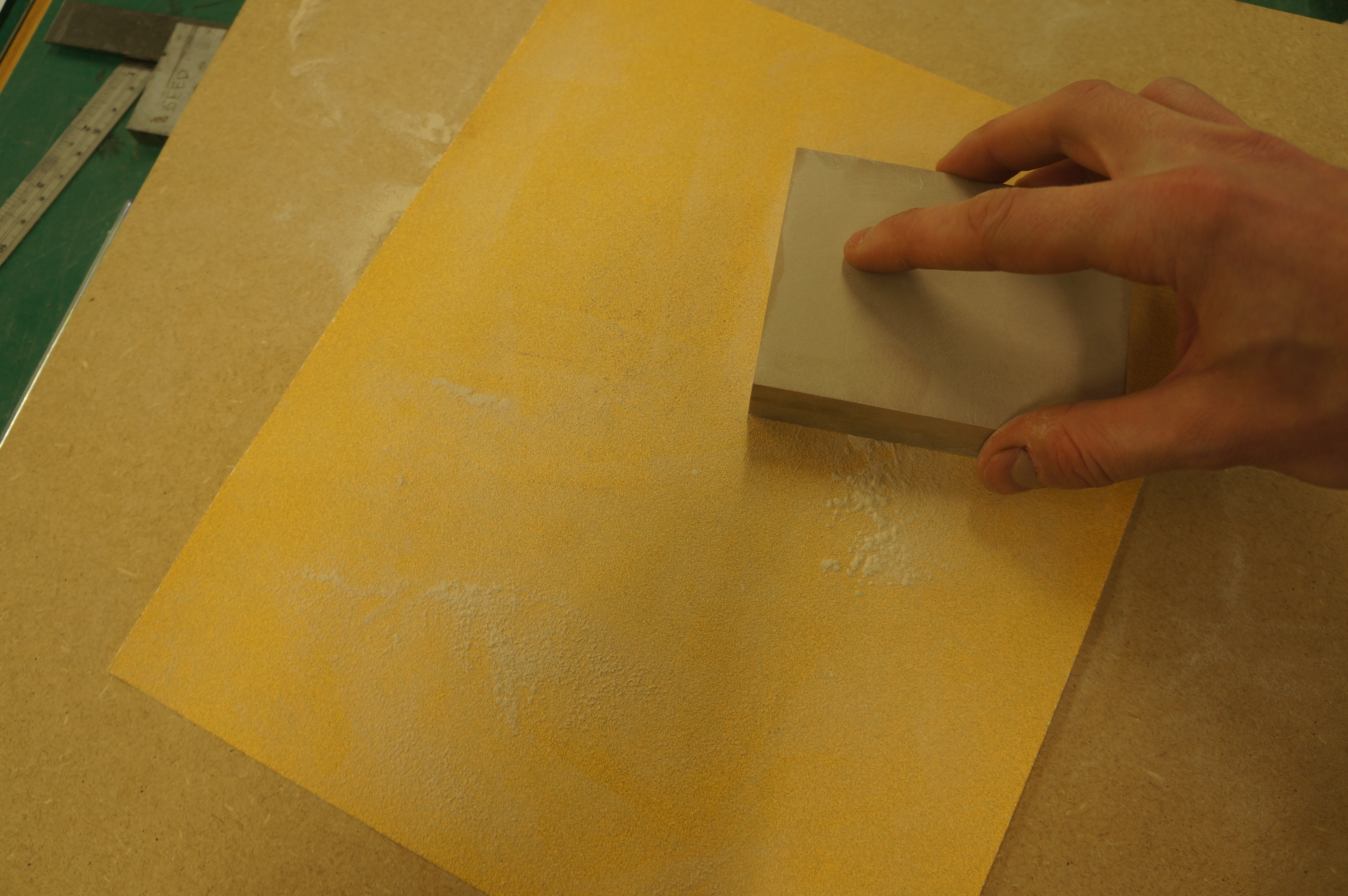
 By putting a piece of sandpaper on a flat board we can easily sand the sawn face of a piece of material to flatten off any saw marks. With chemi-wood in particular this is very straight forward and gives a smooth clean finish. Taking the time to remove saw marks at each stage of production will save time in the long run and helps to keeps the resulting components looking crisp.
Creating a pitched roof
Accurately marking on guides when creating a pitch is recommended as without them we can only presume the machines are set accurately which, given the number of people who use our workshop, is often doubtful!
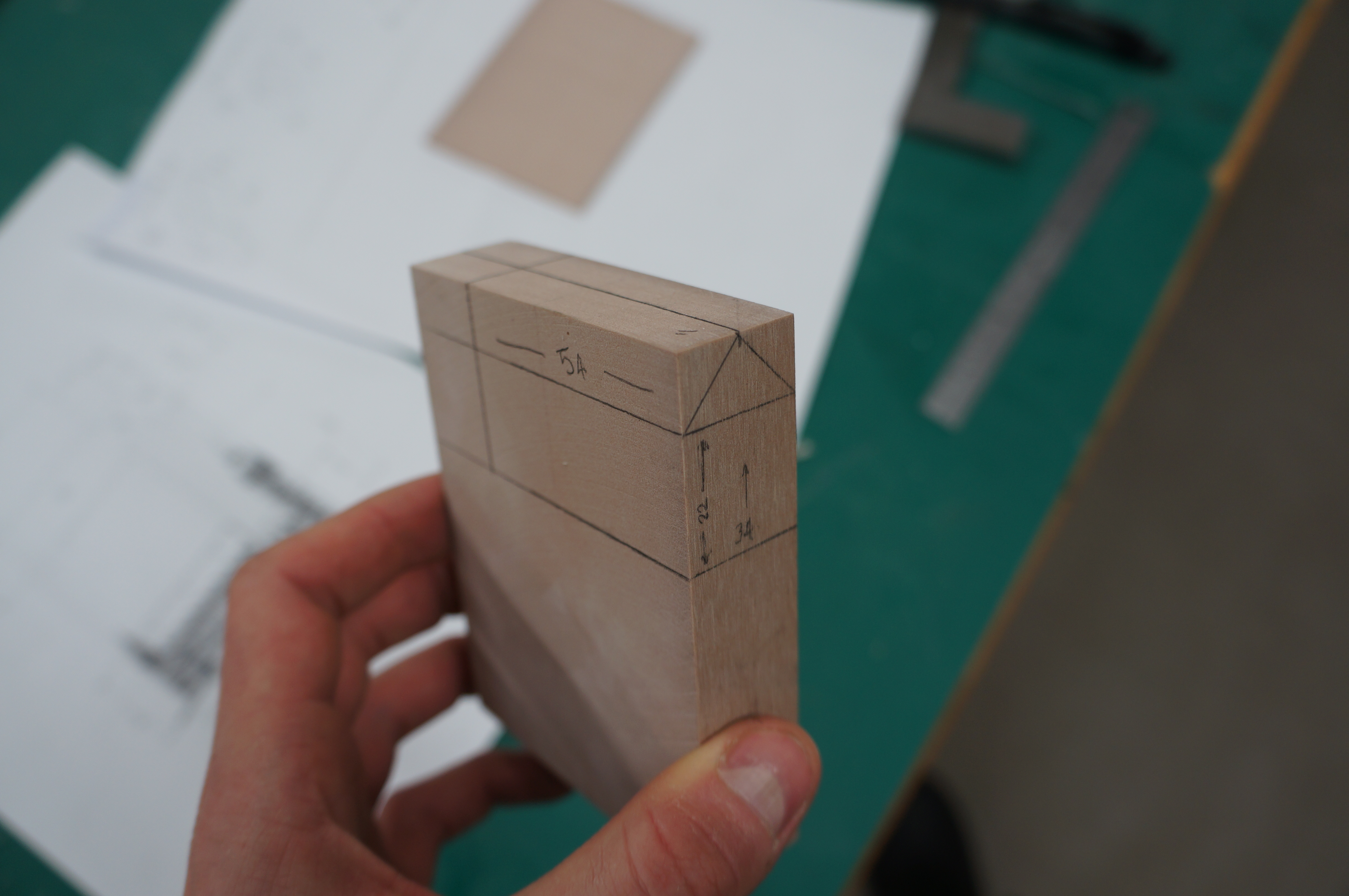
 Once the piece has been cut to the required length it can then be sanded down using the disc sander, in this case removing the minimal amount of material on the edge to create the pitch as marked. Blocks with larger areas to be removed should be cut down closer to the marked line before sanding to avoid burning out the sanding discs and creating excessive force on the machine. Note that I have marked the pitch at the end of the piece to ensure there is enough material to hold on to whilst sanding reducing risk of injury. Always check your marked guide lines as you go.
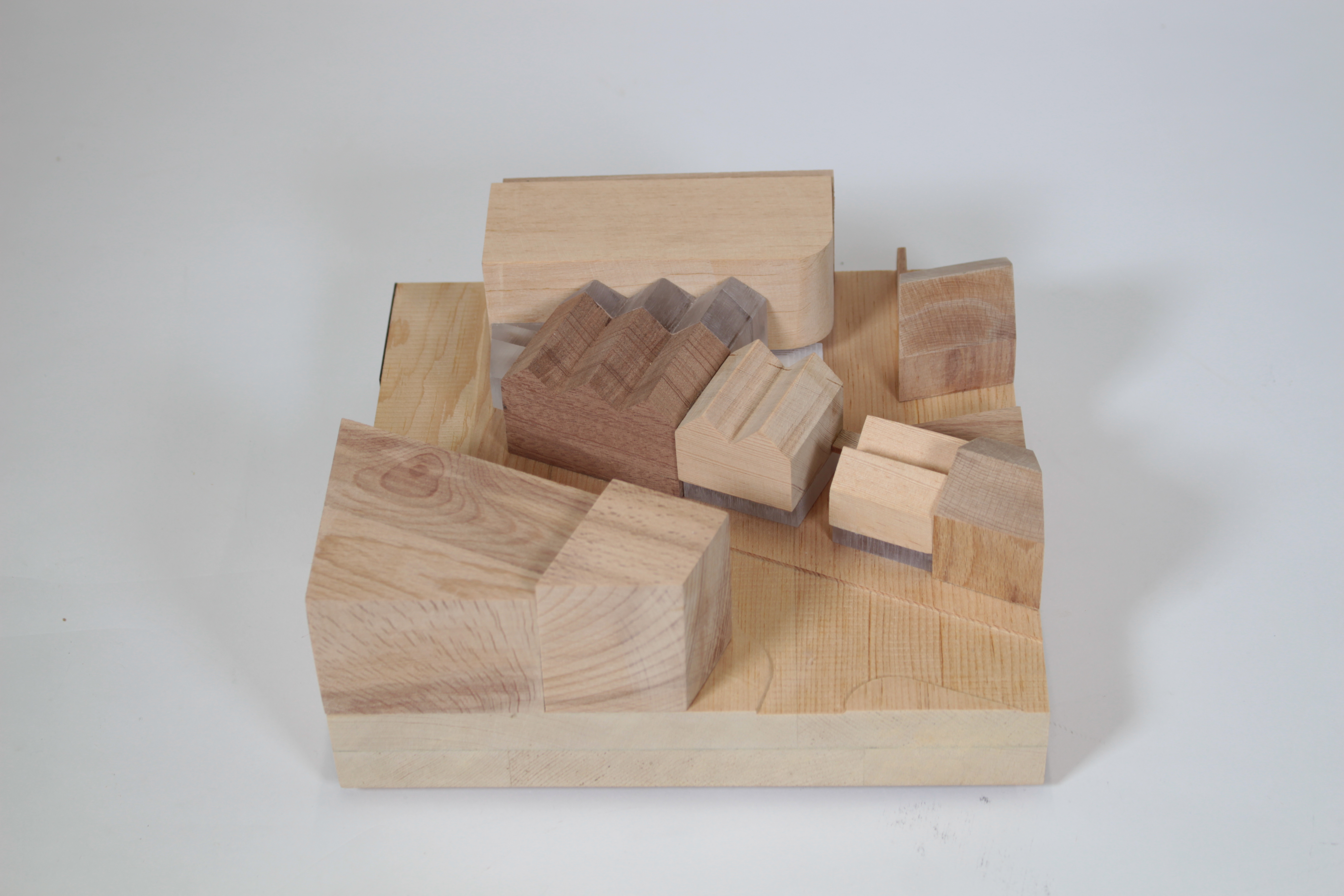
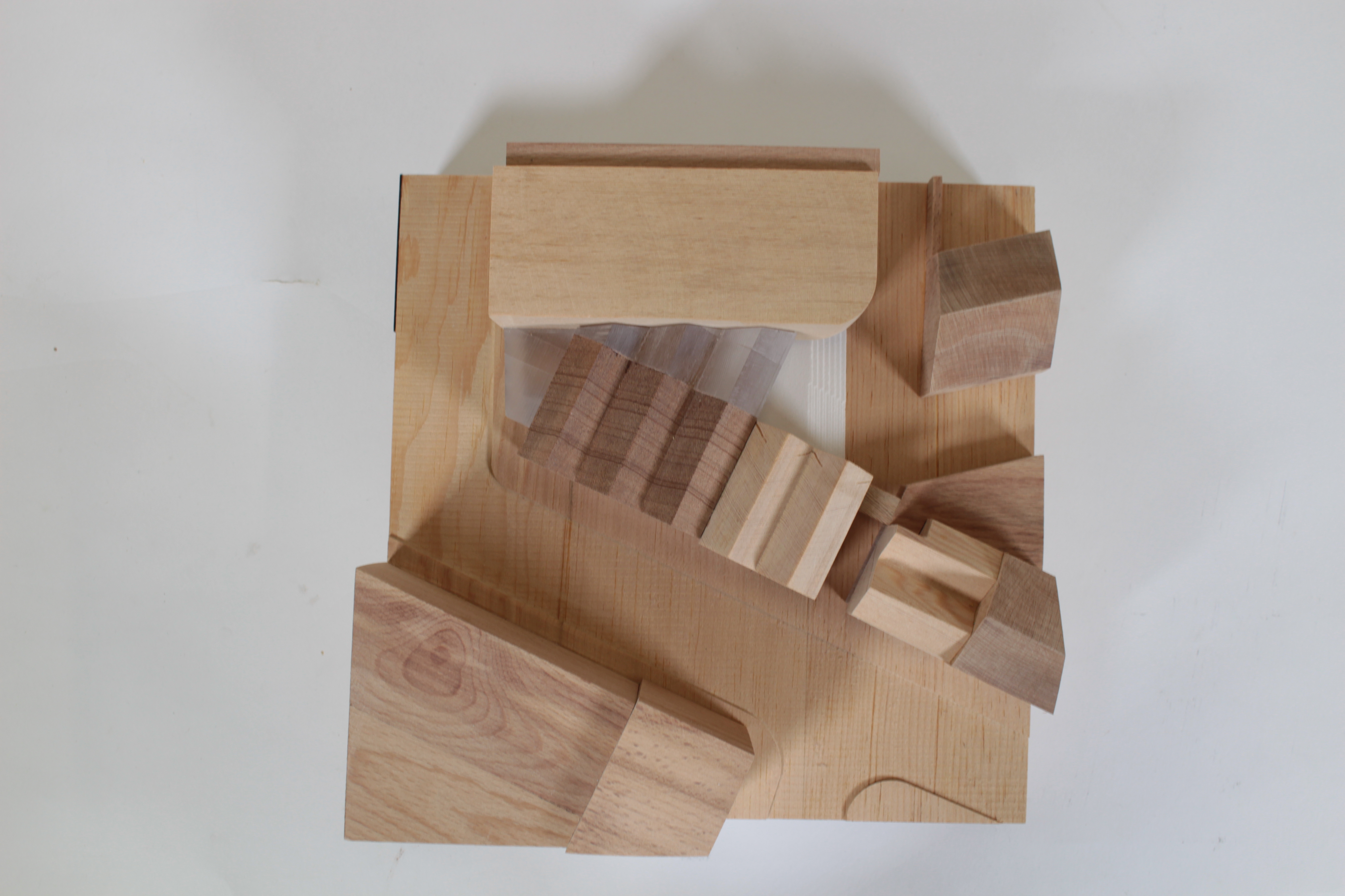
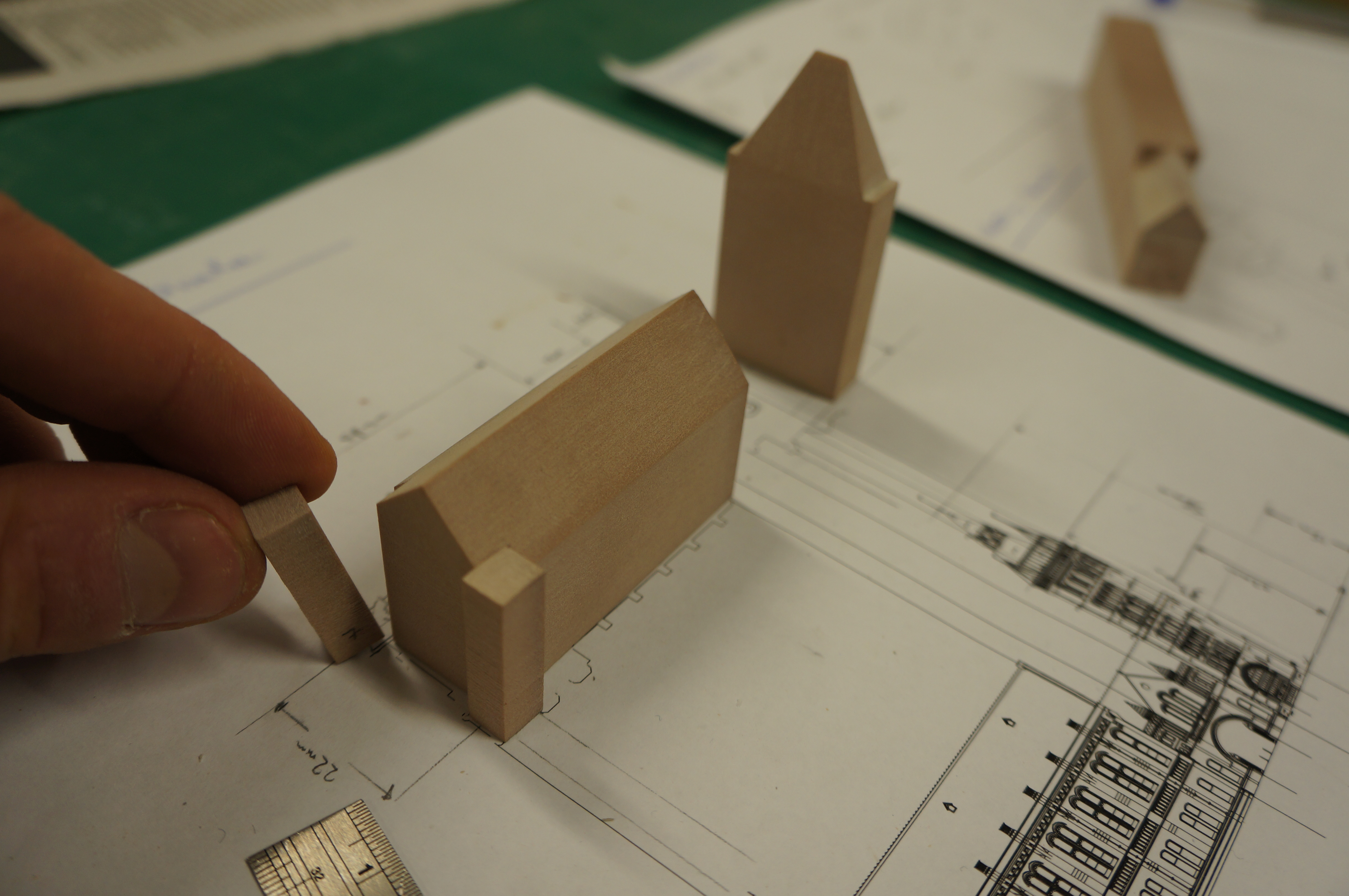
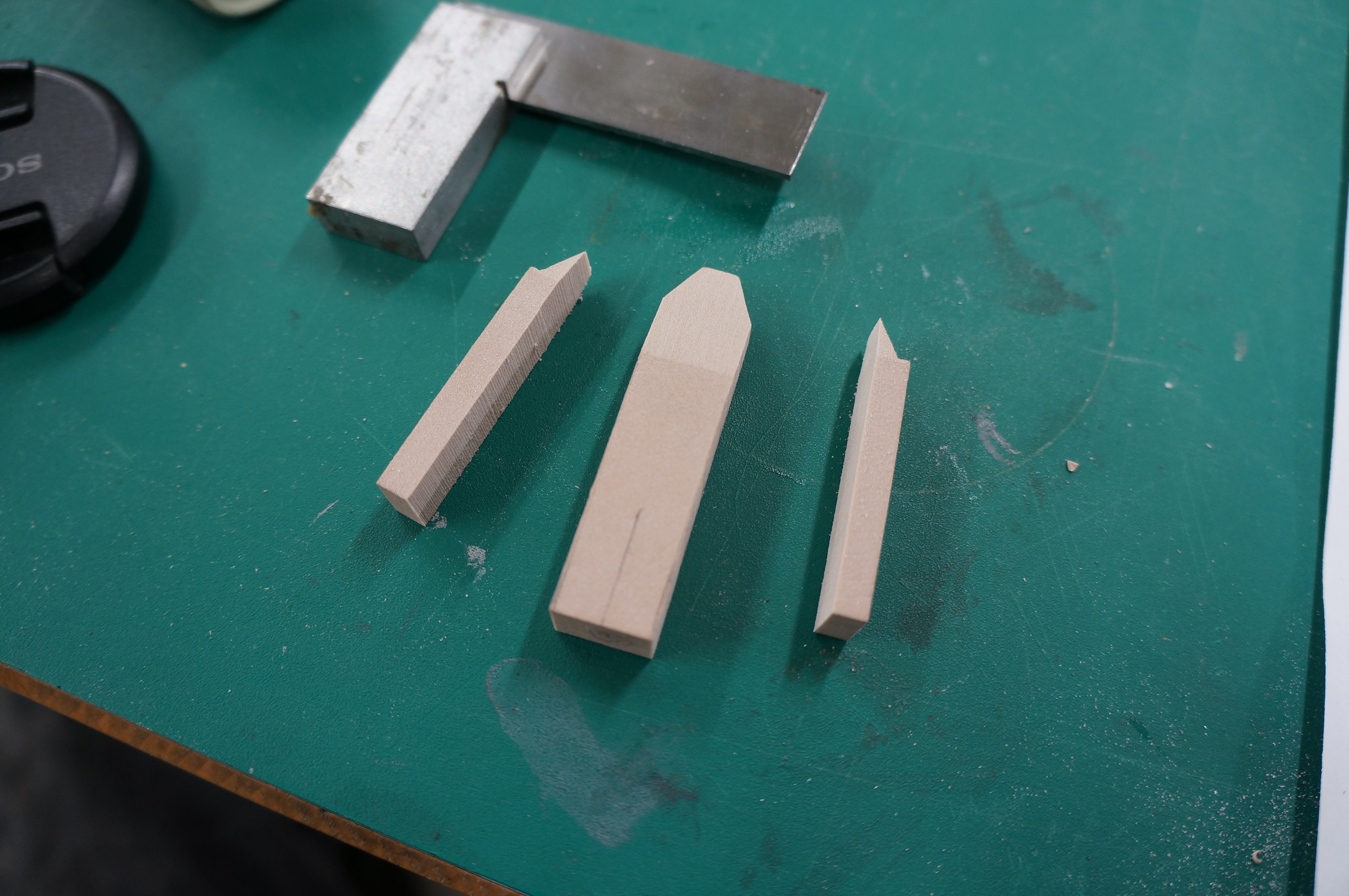
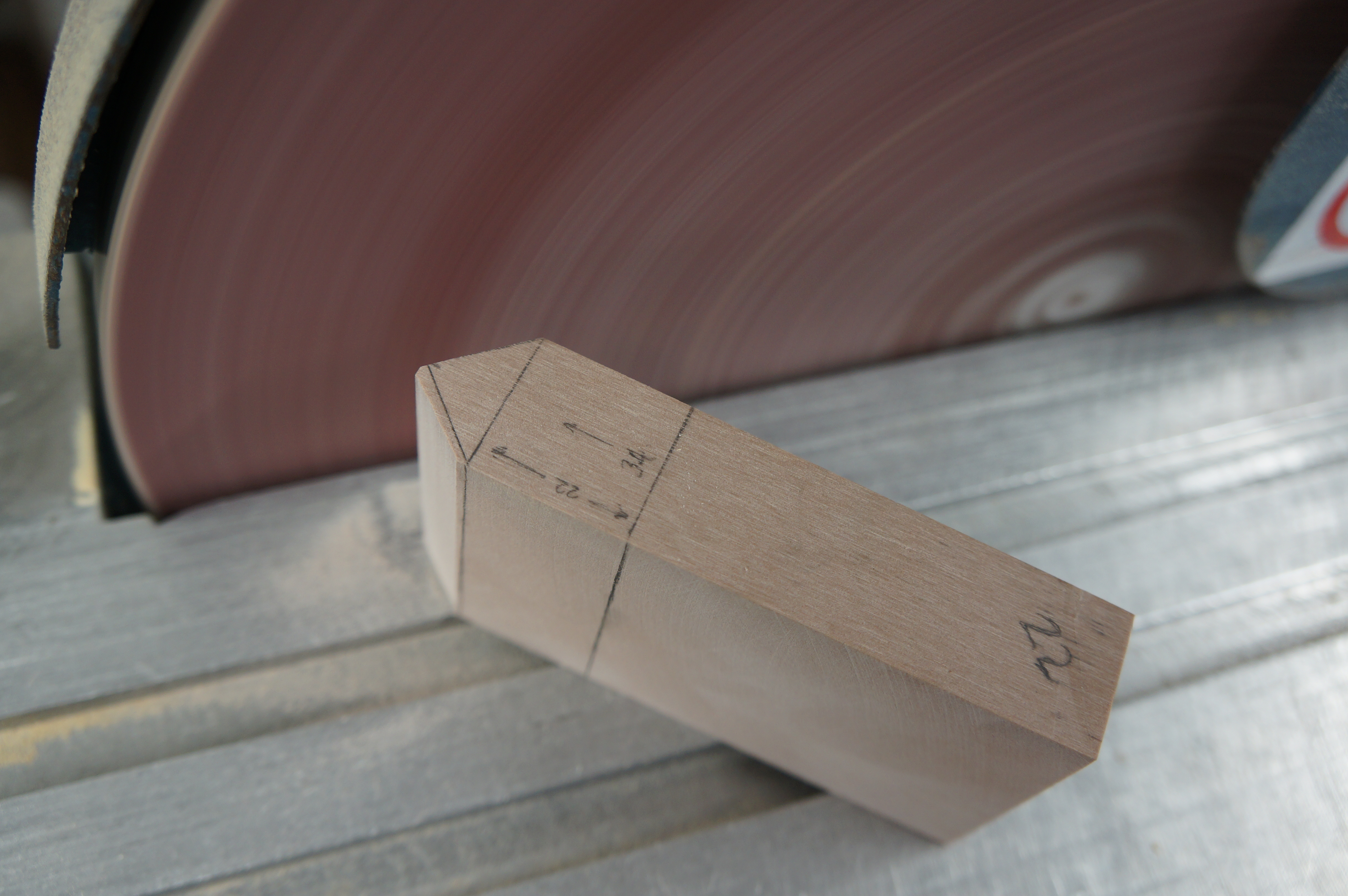 Once the pitch is complete the piece can be removed from the block.
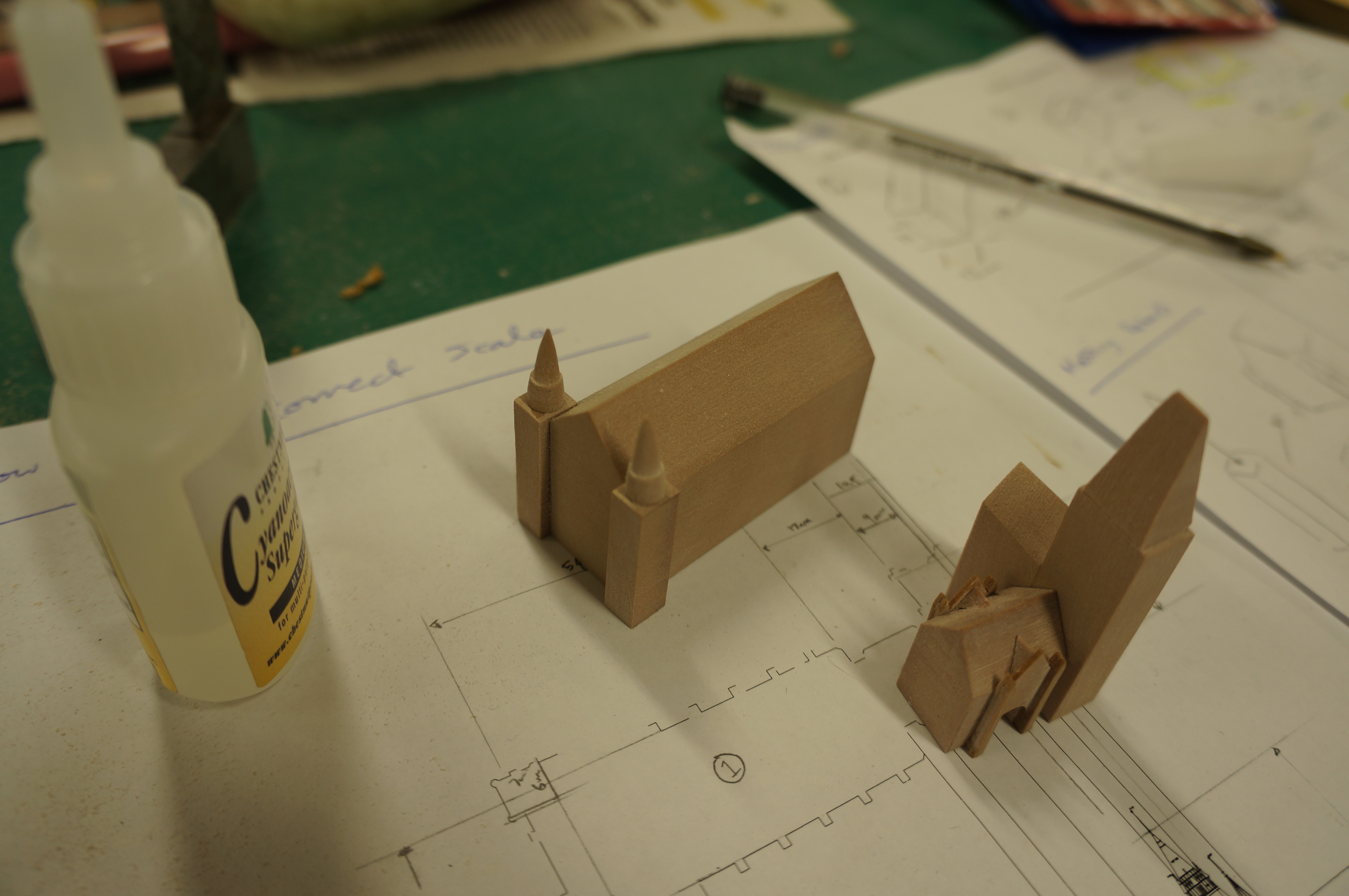
 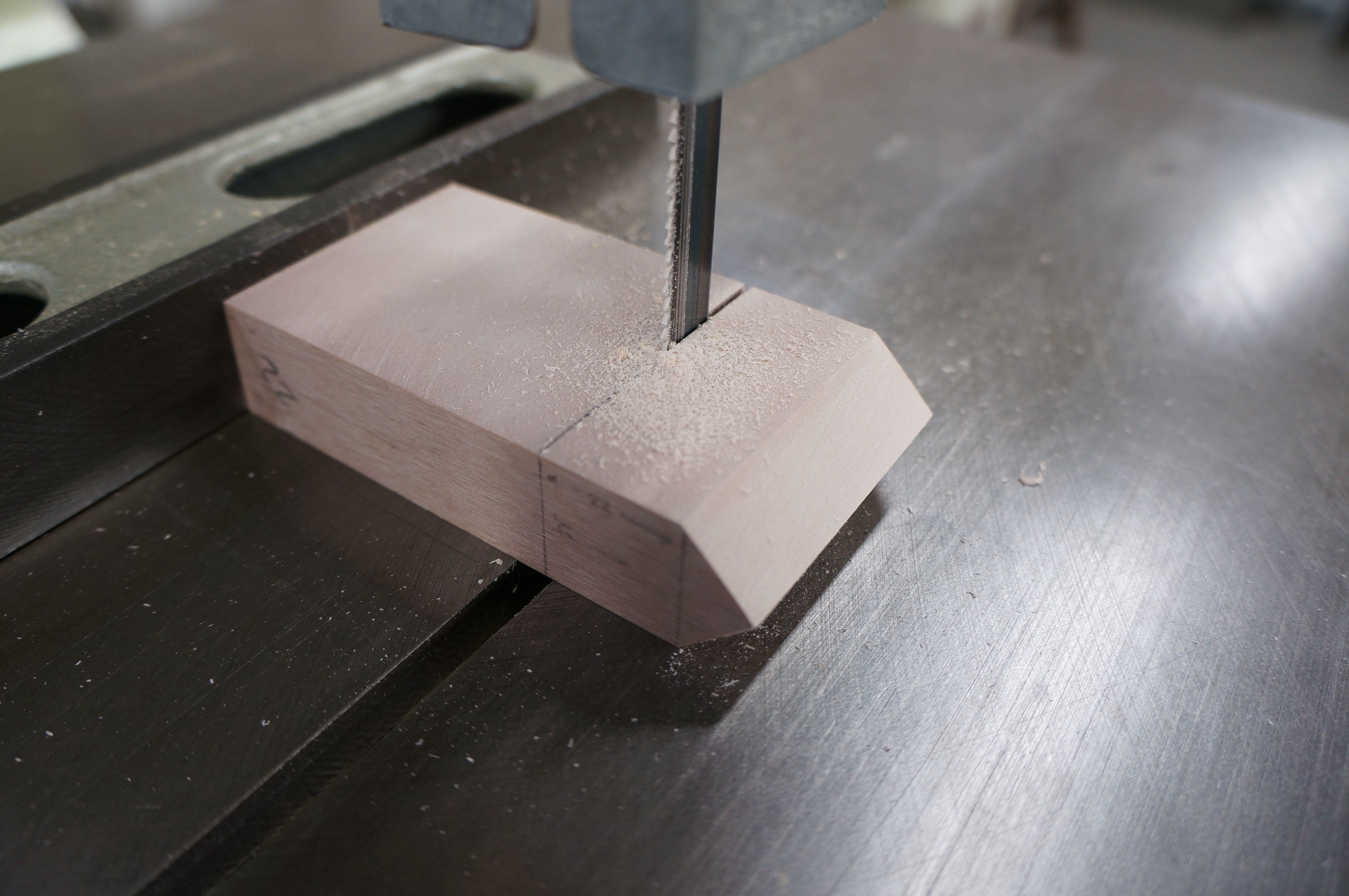 Smaller components that require pitches can sometime be achieved as part of a bigger block using the end of a longer strip of material as shown below. Again this was created using the disk sander and clear marking as a guide. For now this piece will remain attached until the massing detail has been added.
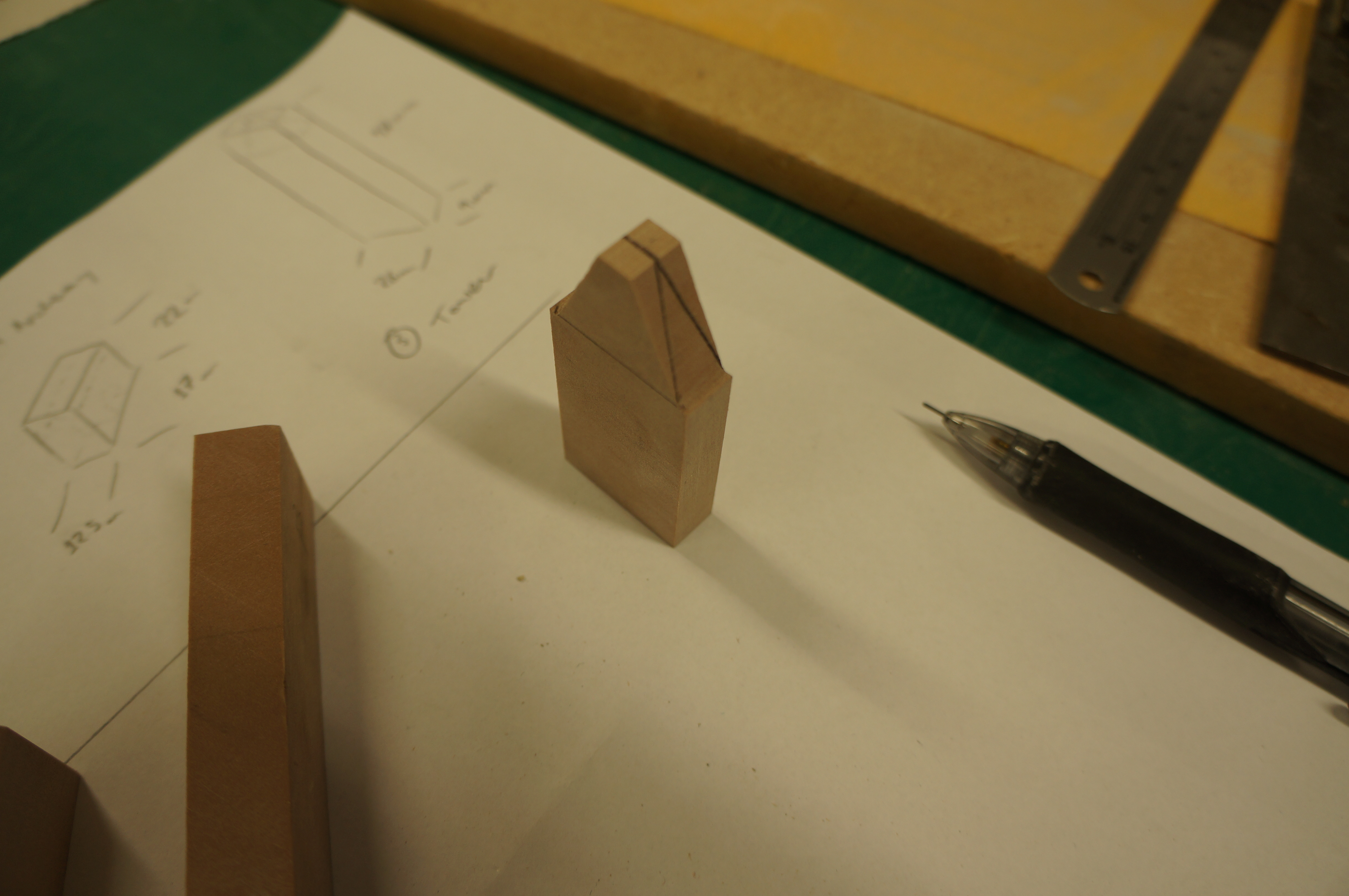
 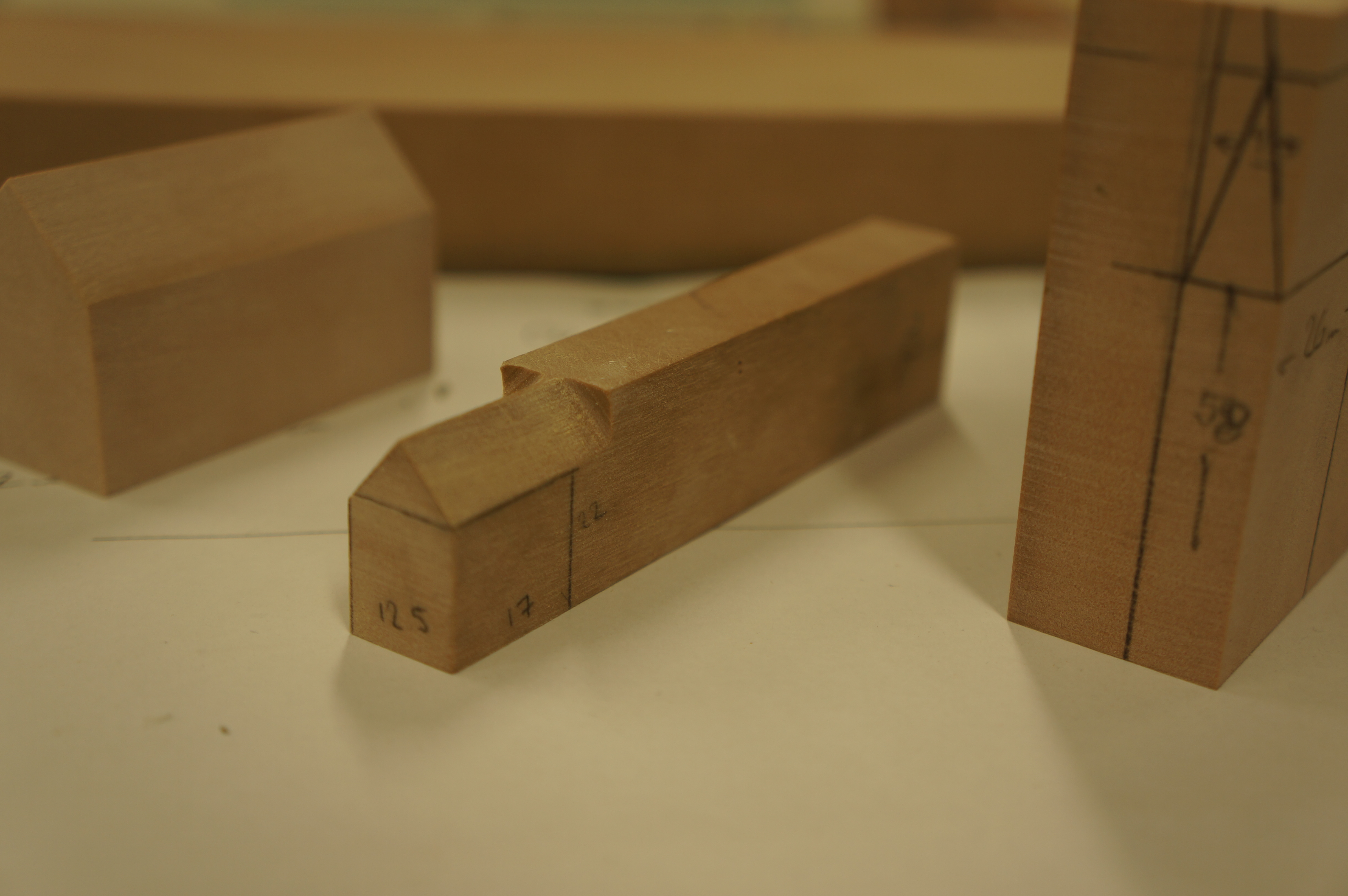 The tower section was measured out from the plan and two-stage pitch added. This photograph shows the second pitch marked out ready to be sanded.
Massing Details
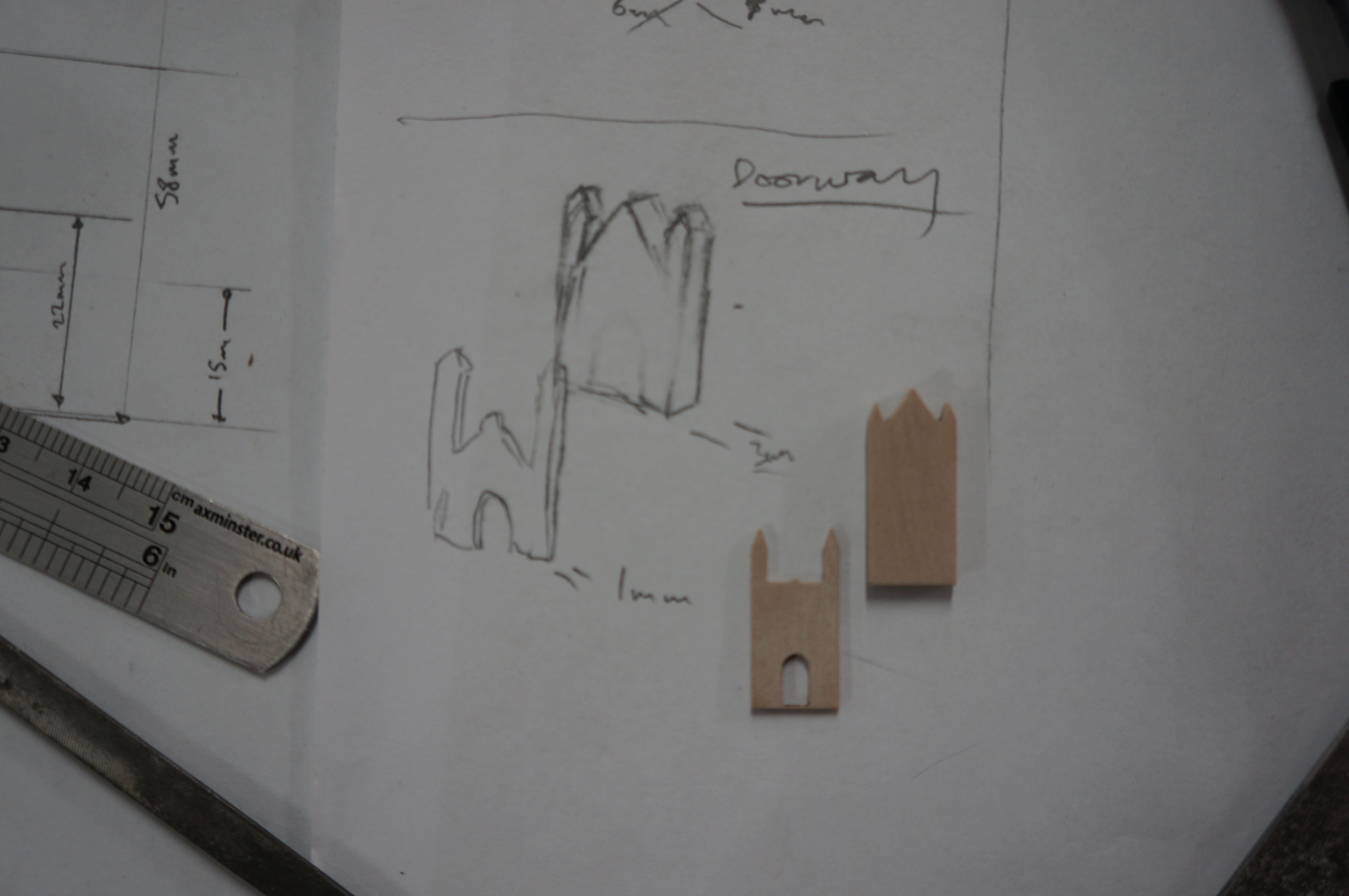
The second phase of the model is to establish what details need to be added to take the blocks to a more familiar form. As with all models a level of detail needs to be established across all components. In this case the archway and repeated buttress’s are of notable presence and so provided the basis for the other relief details as sketched below.
 Using the thin sheet off-cut from the first block, I took the elevation details of the archway from the CAD drawings and created the archway port surround and turret details by layering the two. Laser cutting is great for such intricate parts but presents a problem when finishing due to the fragile nature of such thin components. Care had to be taken when sanding off burn marks so spare components can come in handy if there are any breakages.
 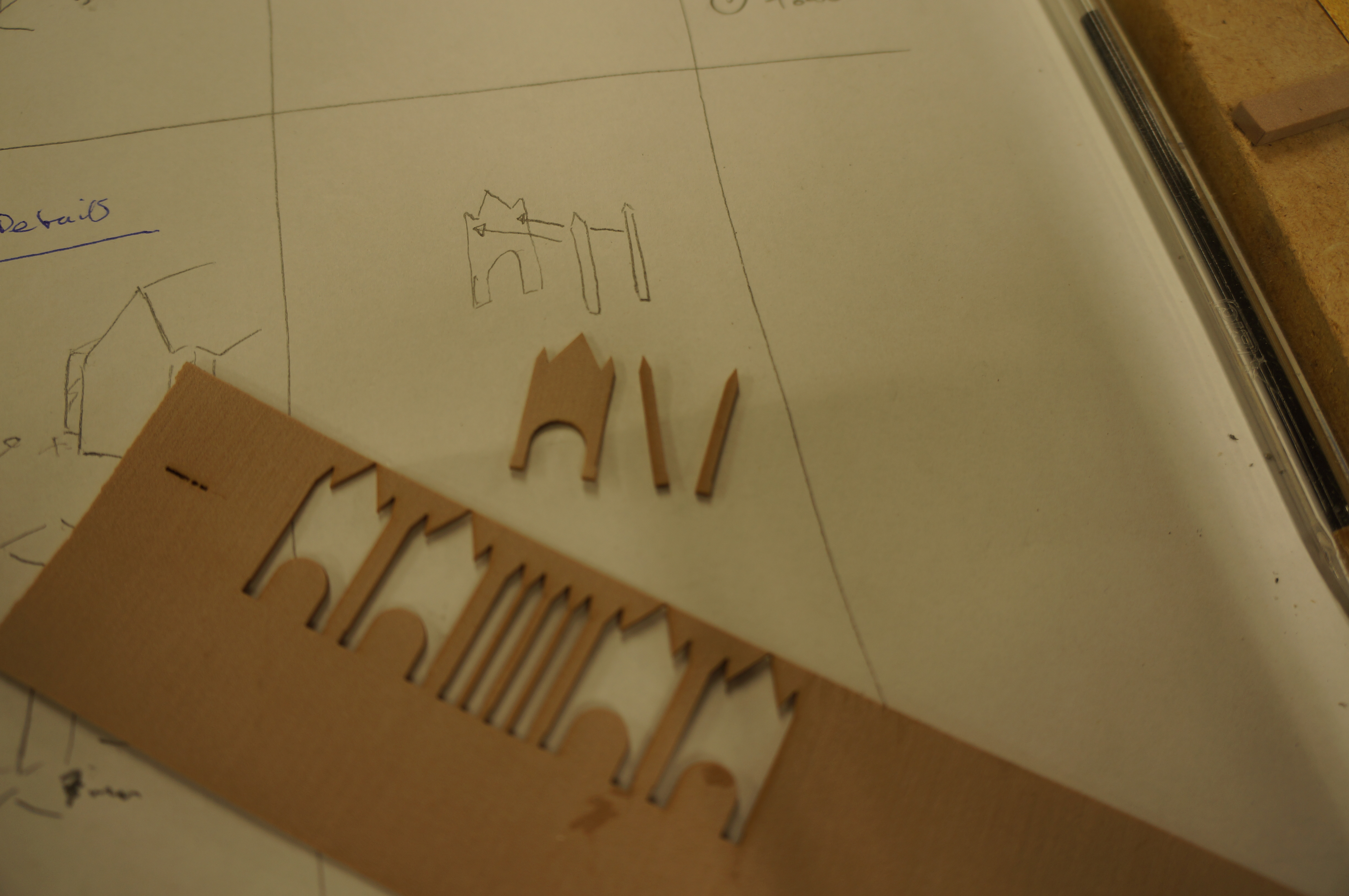 I used a medium thickness cyanoacrylate ( AKA superglue) to carefully stick the layered details together. Only small spots of glue were used and can be applied with the end of a cocktail stick or a scalpel blade.
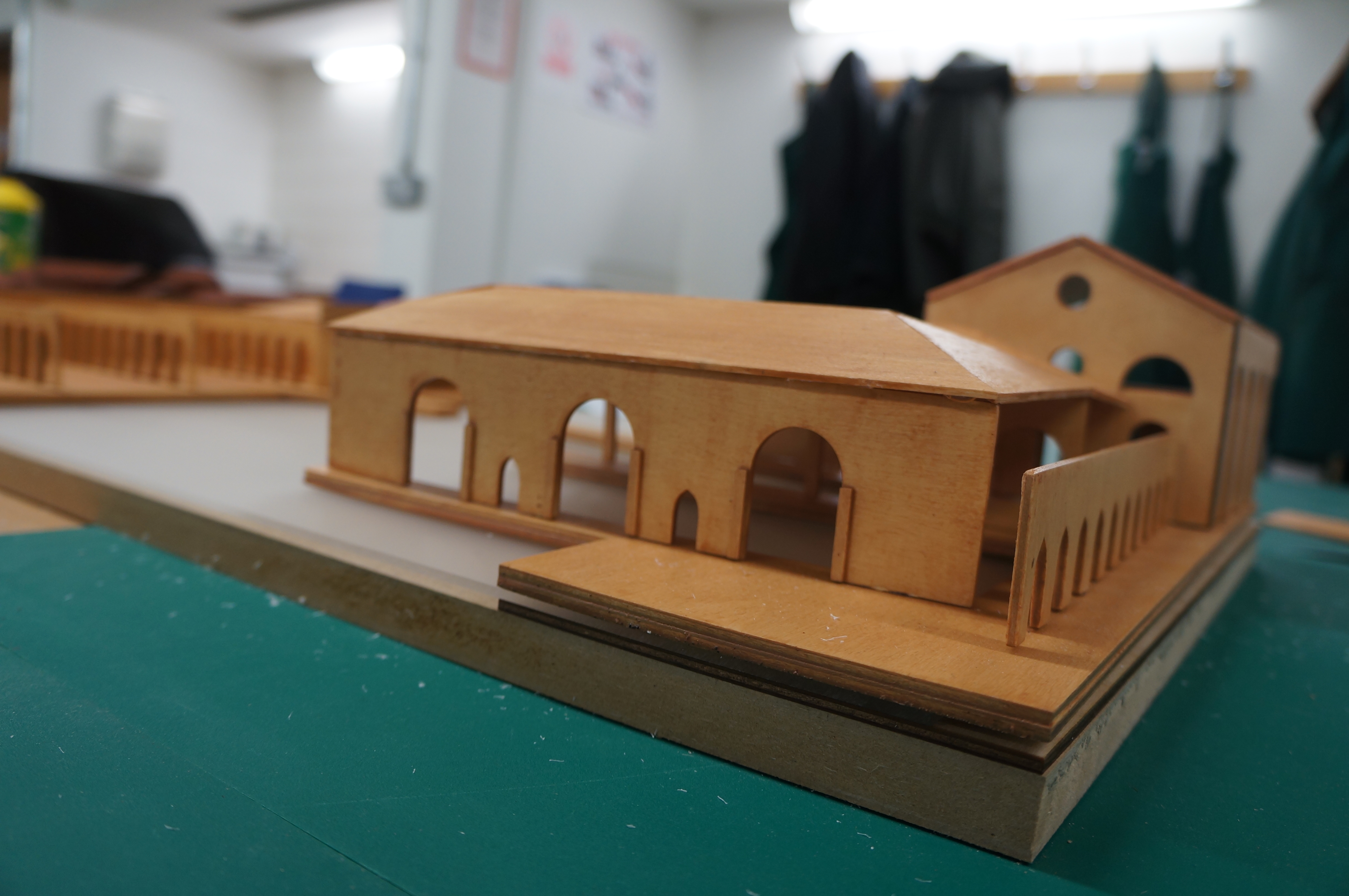
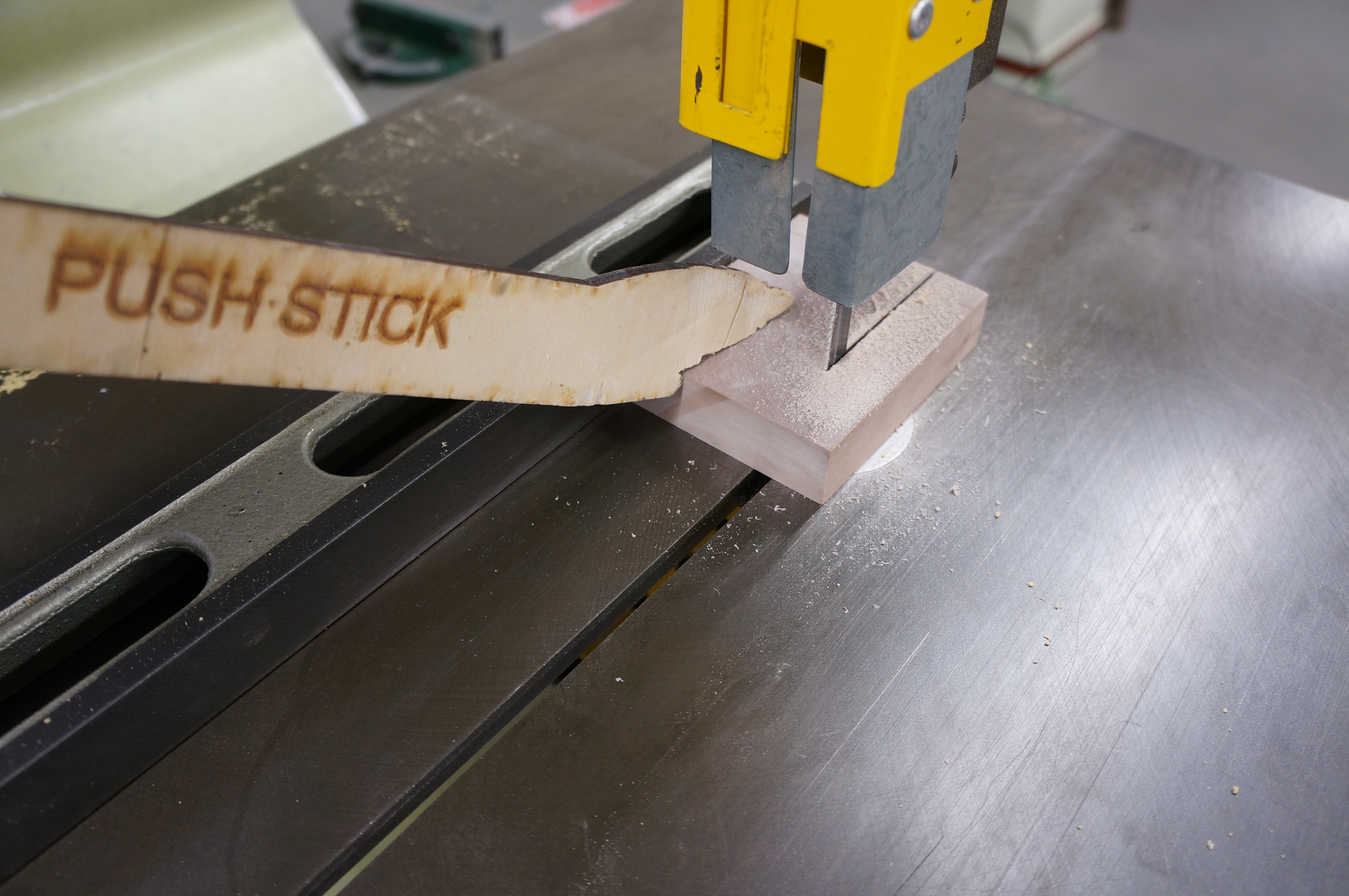
The layered up arch facade can then be applied to the primary massing from earlier taking care to center it as marked. 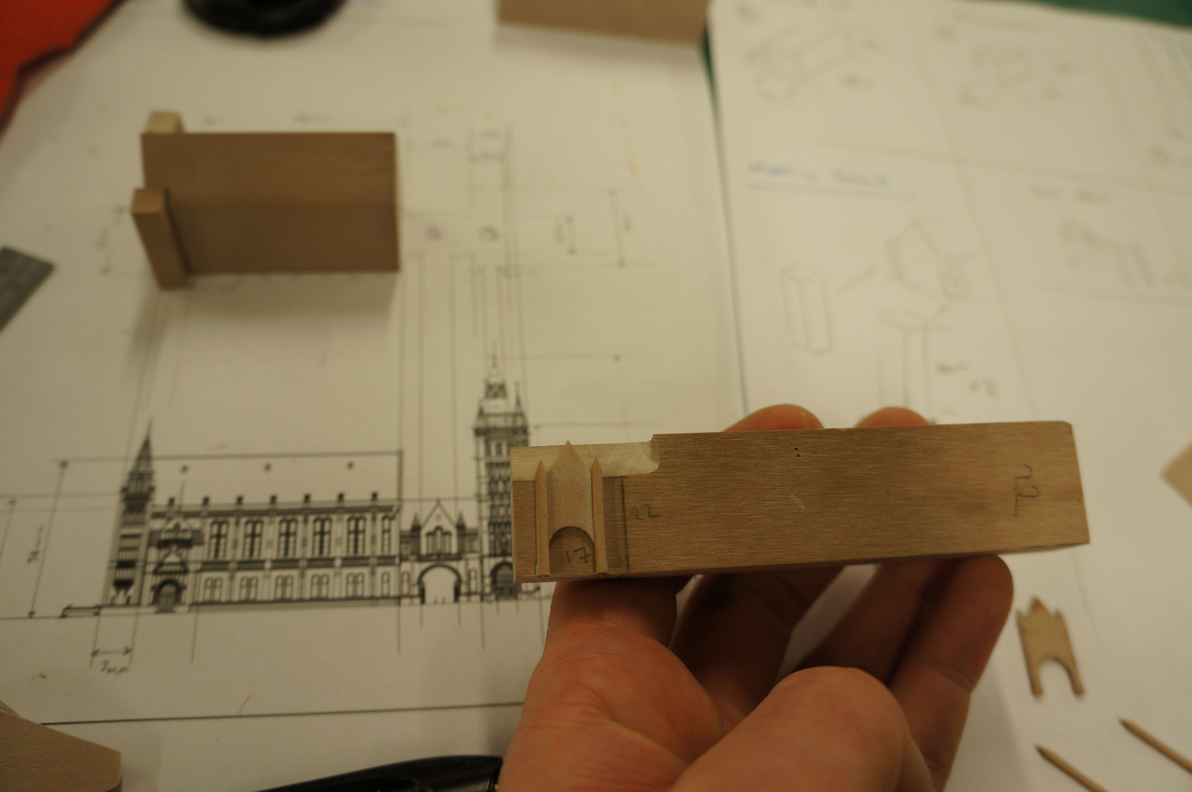 Once fixed the material filling the arch is removed in notches using the bandsaw – controlled easily thanks to the extension we have the piece built on with a push-stick.
 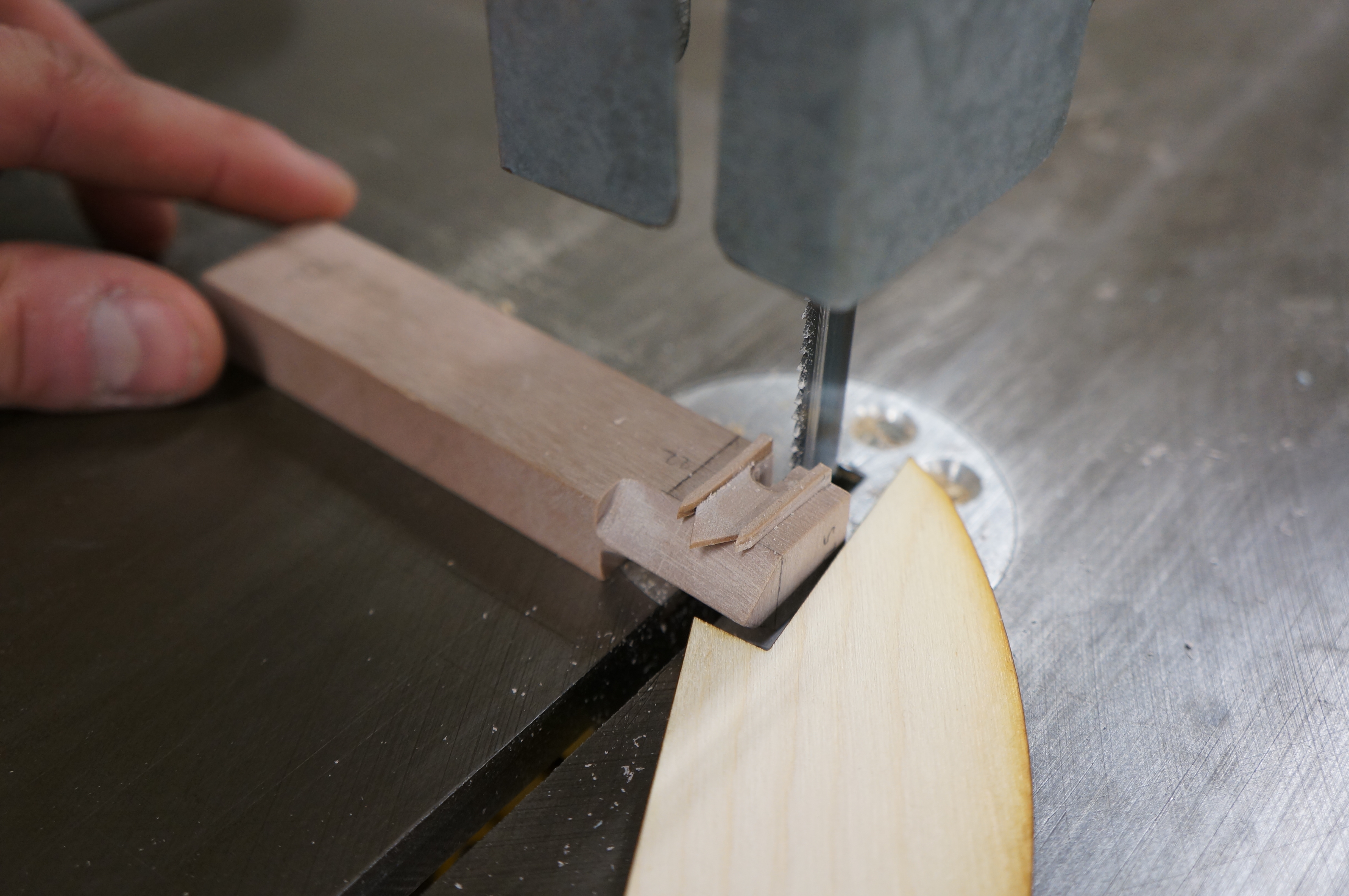 After hand filing the curve of the arch using a round file the piece can be parted off from the extension and excess material carefully sanded back to the marked line taken from our printed scaled plan.
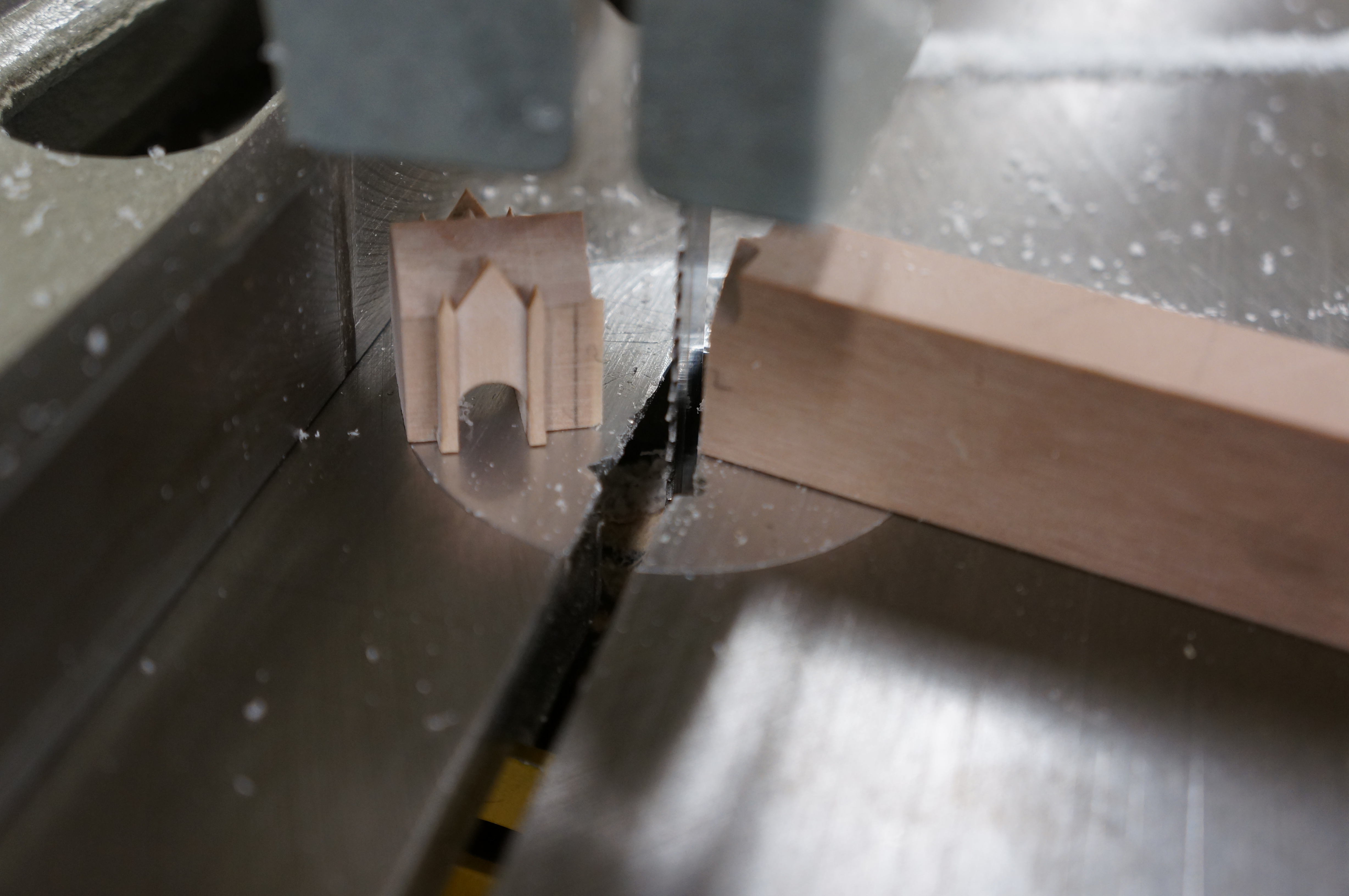
STOP PRESS! MISTAKE DETECTED!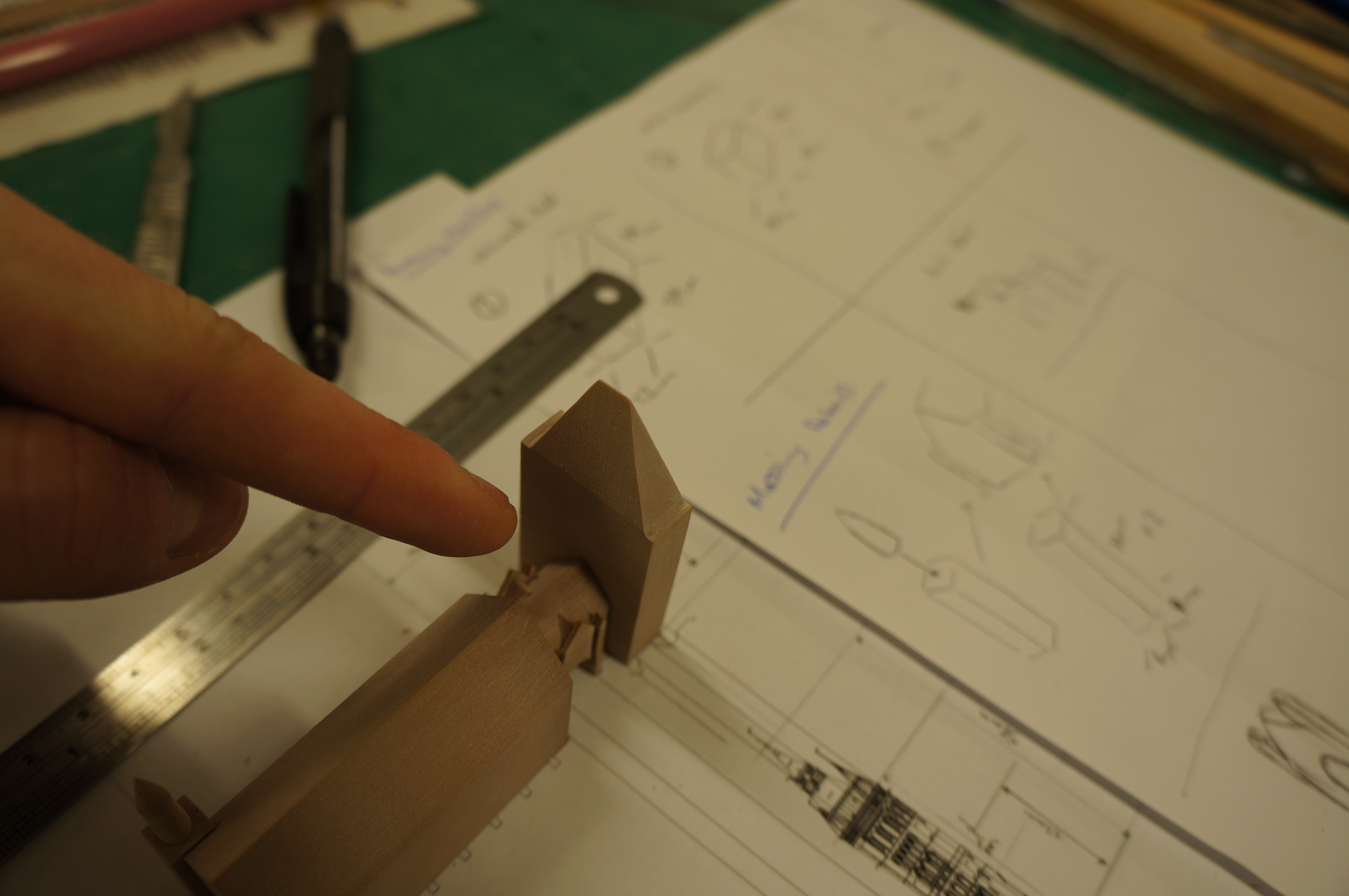 Leaving the workshop and walking down past the Whitworth Hall after work I noticed an error with my model so far in that I had wrongly presumed the footprint of the tower made up the entire plan print as shown. This in fact turns out to be wrong and the tower makes up just over half of the block footprint.
No need to panic!
By reviewing the plans and evaluating the oversight It was easily rectified by modifying the piece using the top center as a reference to reduce the overall size and roof pitch line. We all make mistakes so no need to worry if this happens when your making your model – its how we handle them that matters.
What ever you do don’t ignore it – especially if it is connecting to another part of the model as there is always a knock on effect with errors that will come back to haunt you! Try to take the time to do it right even if it means starting again.
 Massing Details Continued
The next details I made were the spires at the top of the towers on the end of the Whitworth Hall. to create these I took a square section of chemi-wood from the offcuts and fixed it into the chuck of a hand drill.
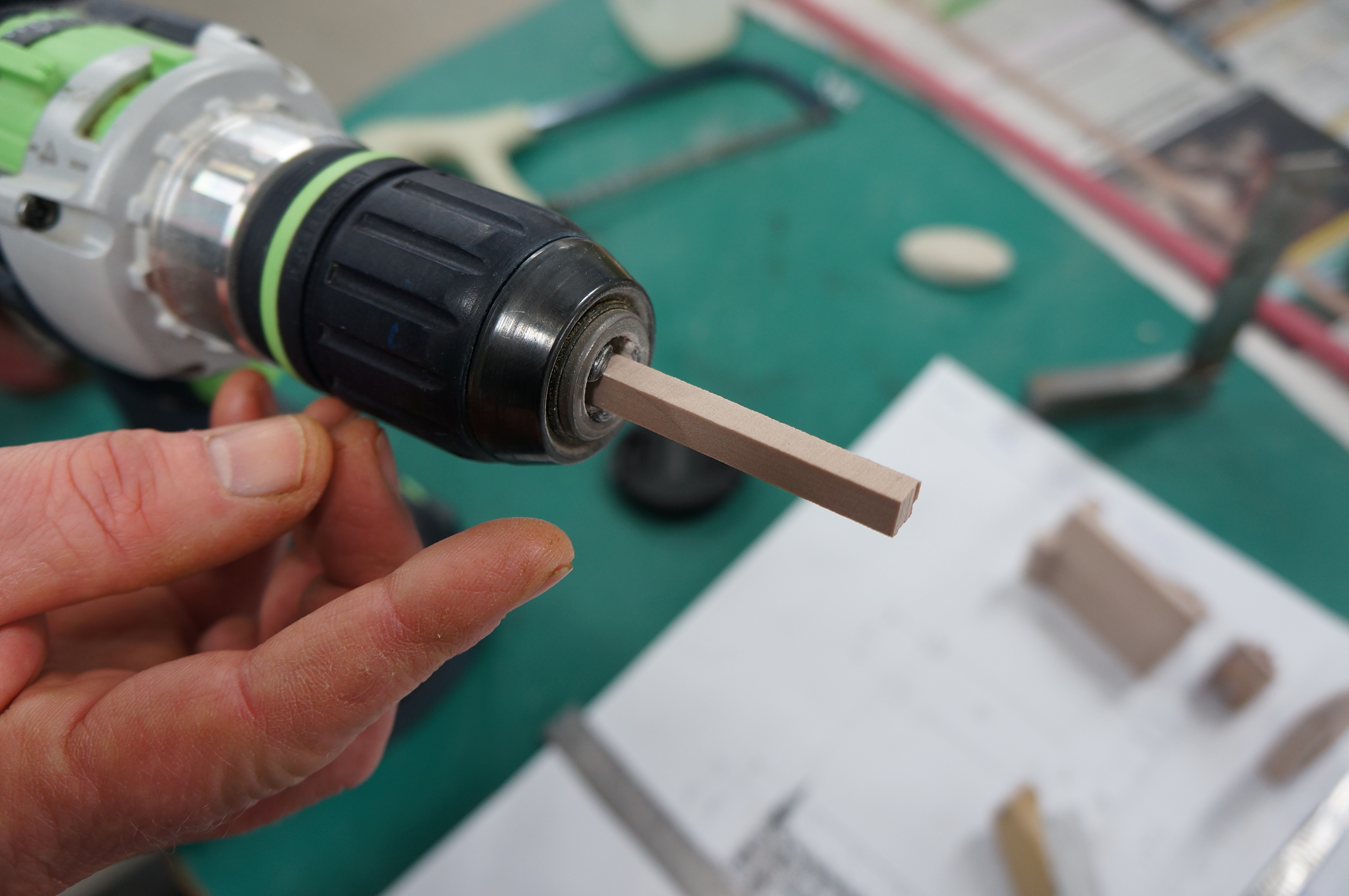 Taking note of the required 6mm radius I used 120 grit sandpaper to reduce the section down to a dowel, regularly checking the size with calipers.
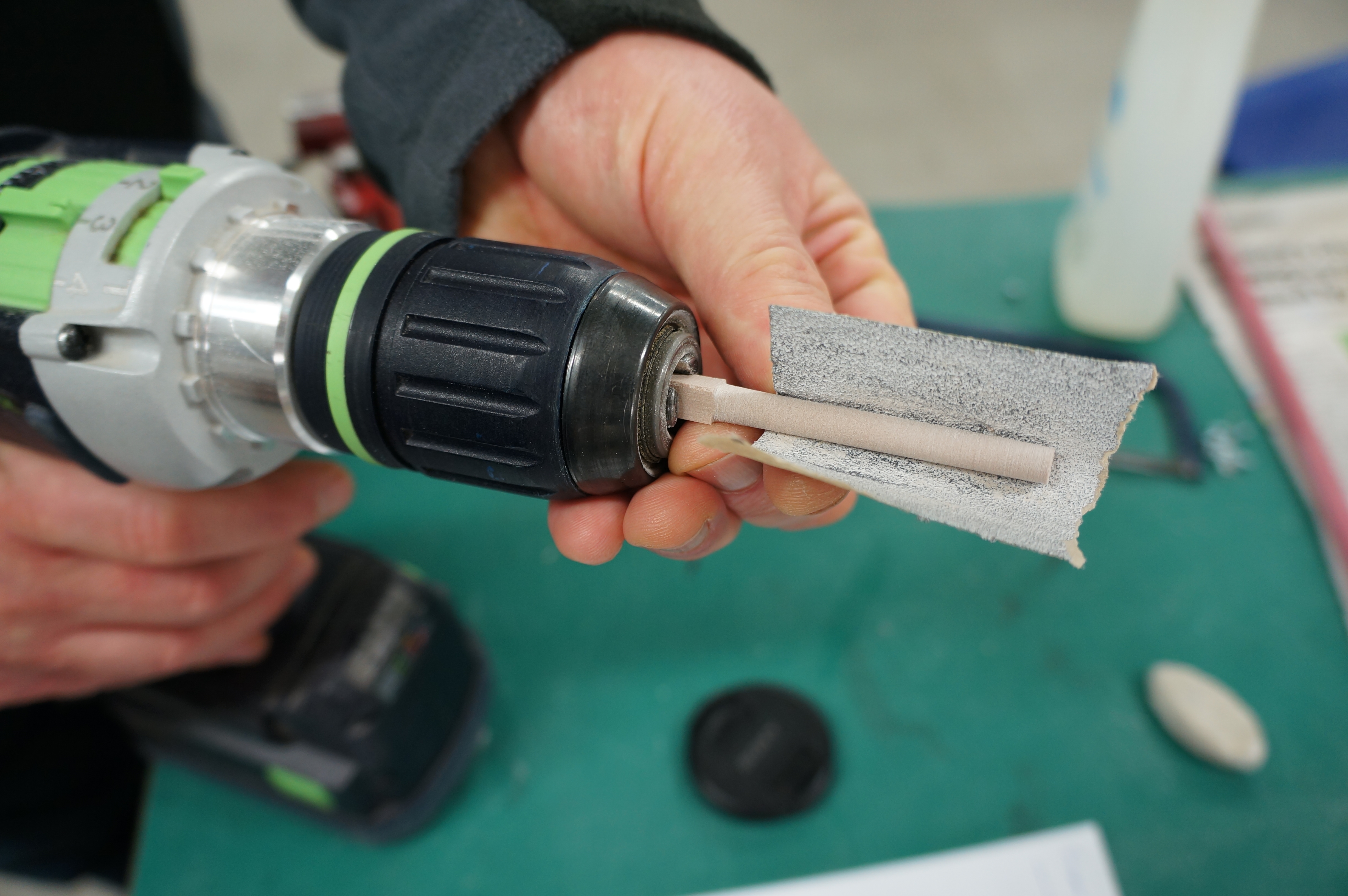 Once the dowel was a 6mm I marked on the low point of the spire and used a needle file to reduce it down to a point before adding a shoulder at the base. The completed spire was then removed with a junior hacksaw before being lightly sanded flat at the base.

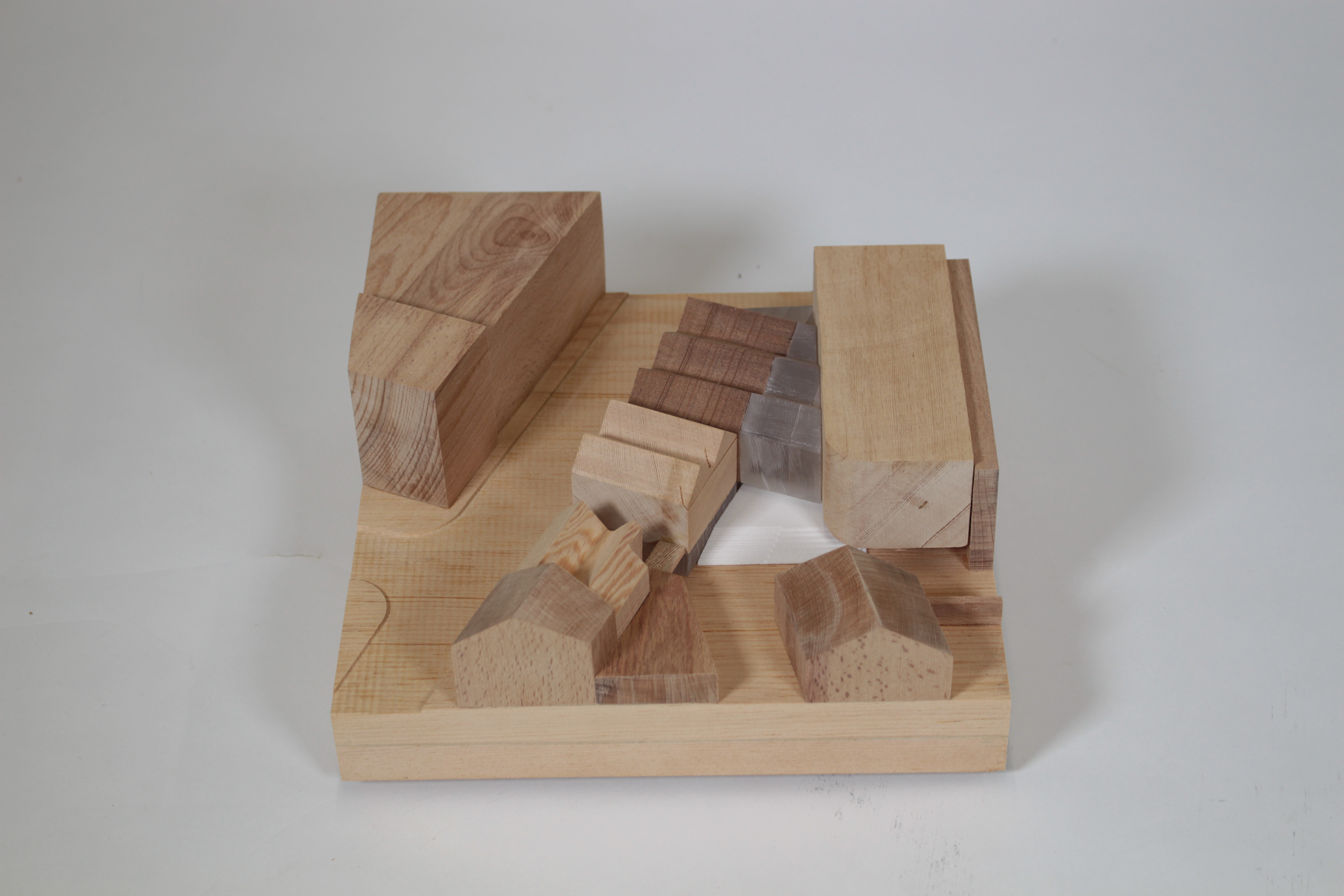
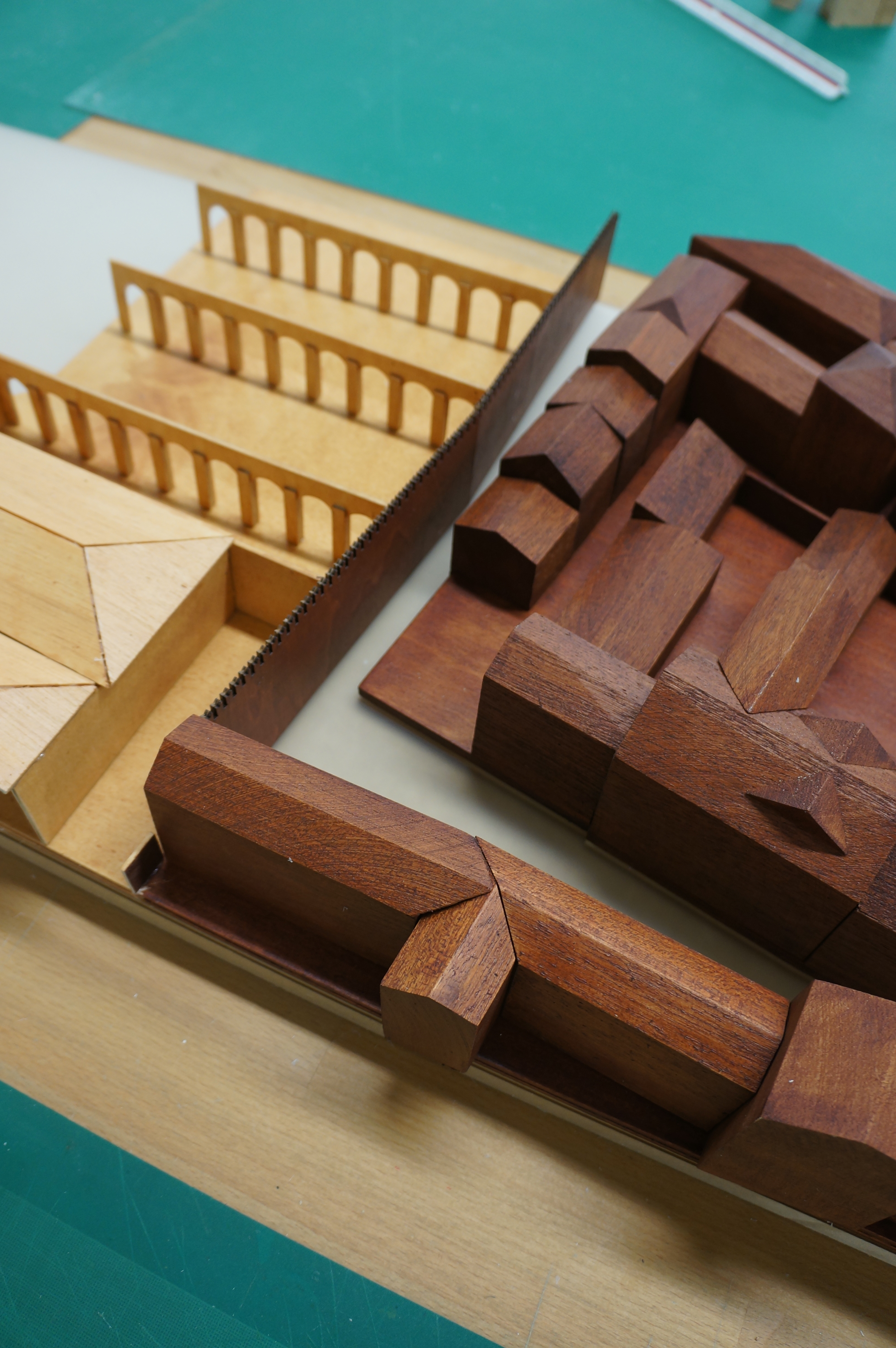
 The buttresses along each side of the Whitworth hall were made using thin strips that were layered up (shown below) on top of each other having been cut to the specified step heights.
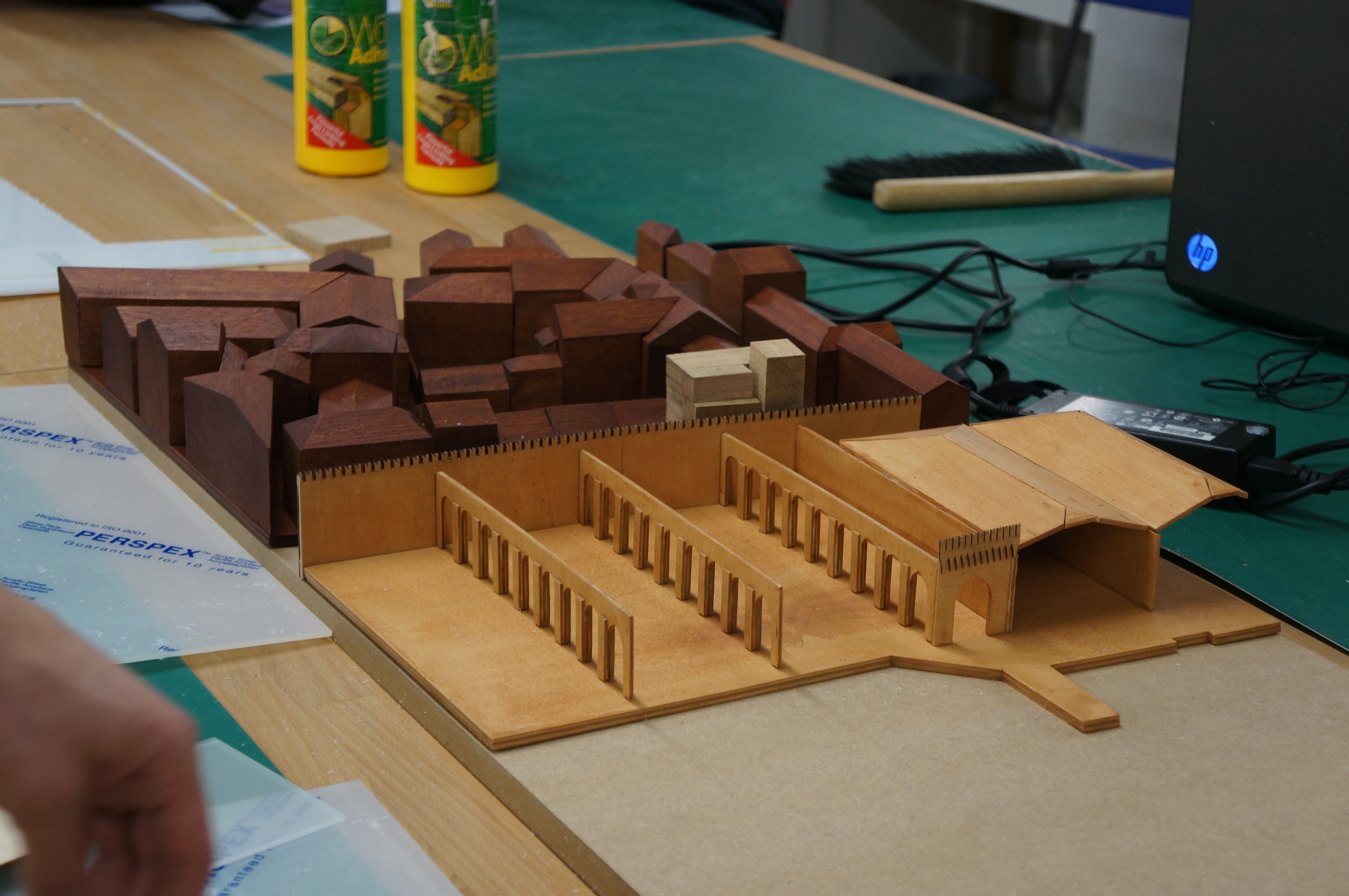
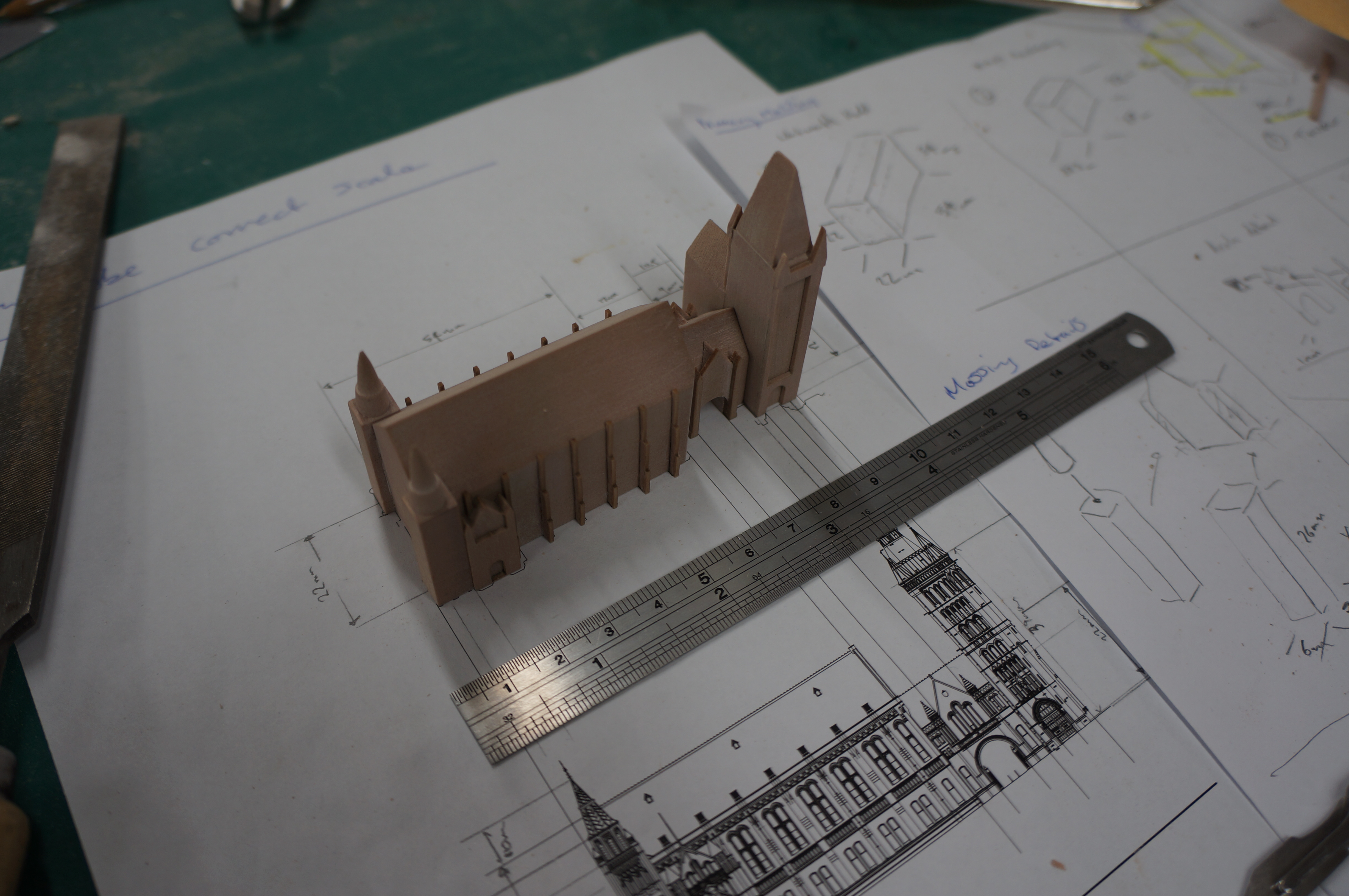
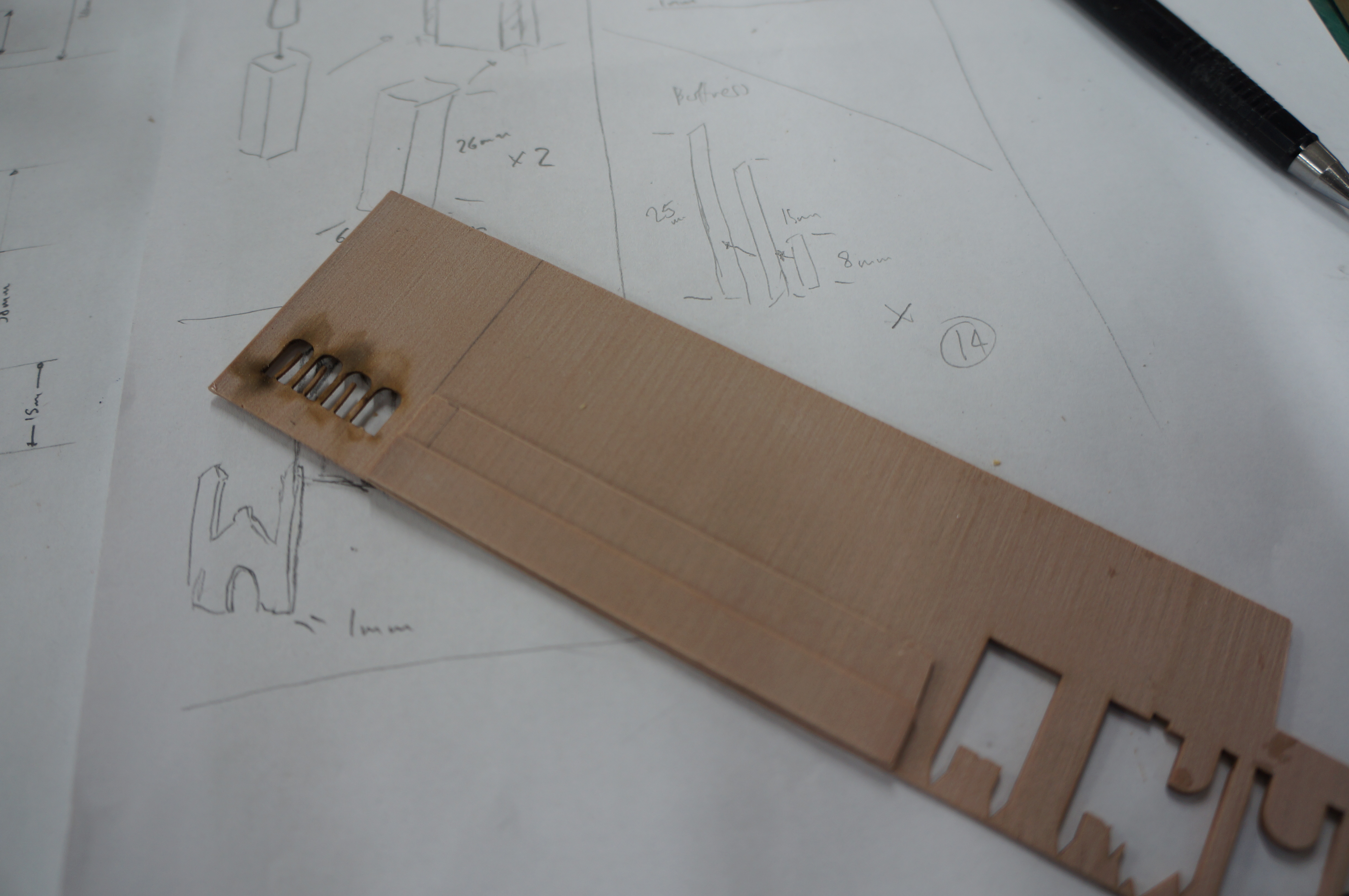 Once fixed I put this piece into the laser cutter and cut strips through the joined layers creating the buttress profiles. These were then carefully fixed in place using small amounts of cynoacrylate.
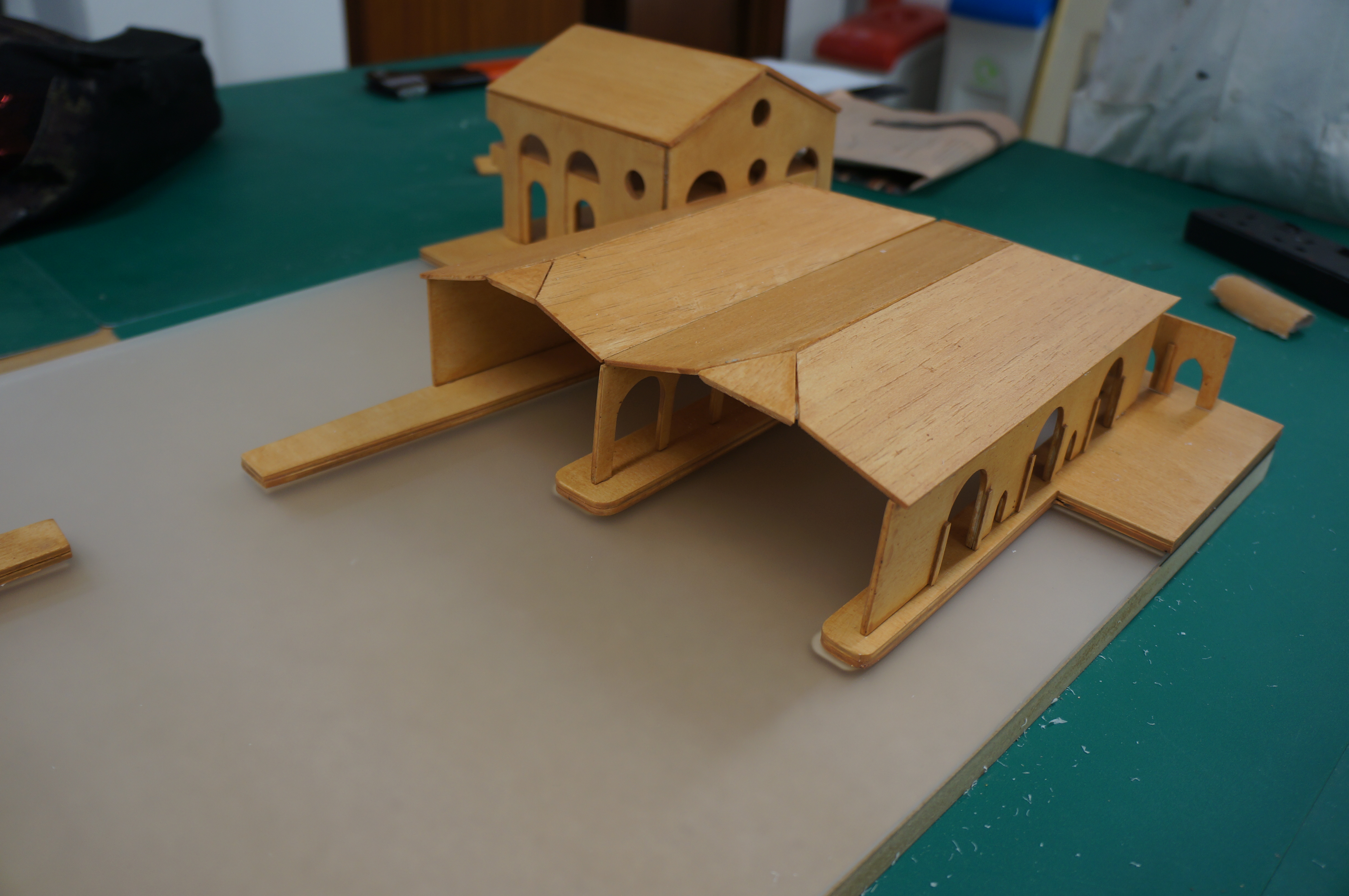
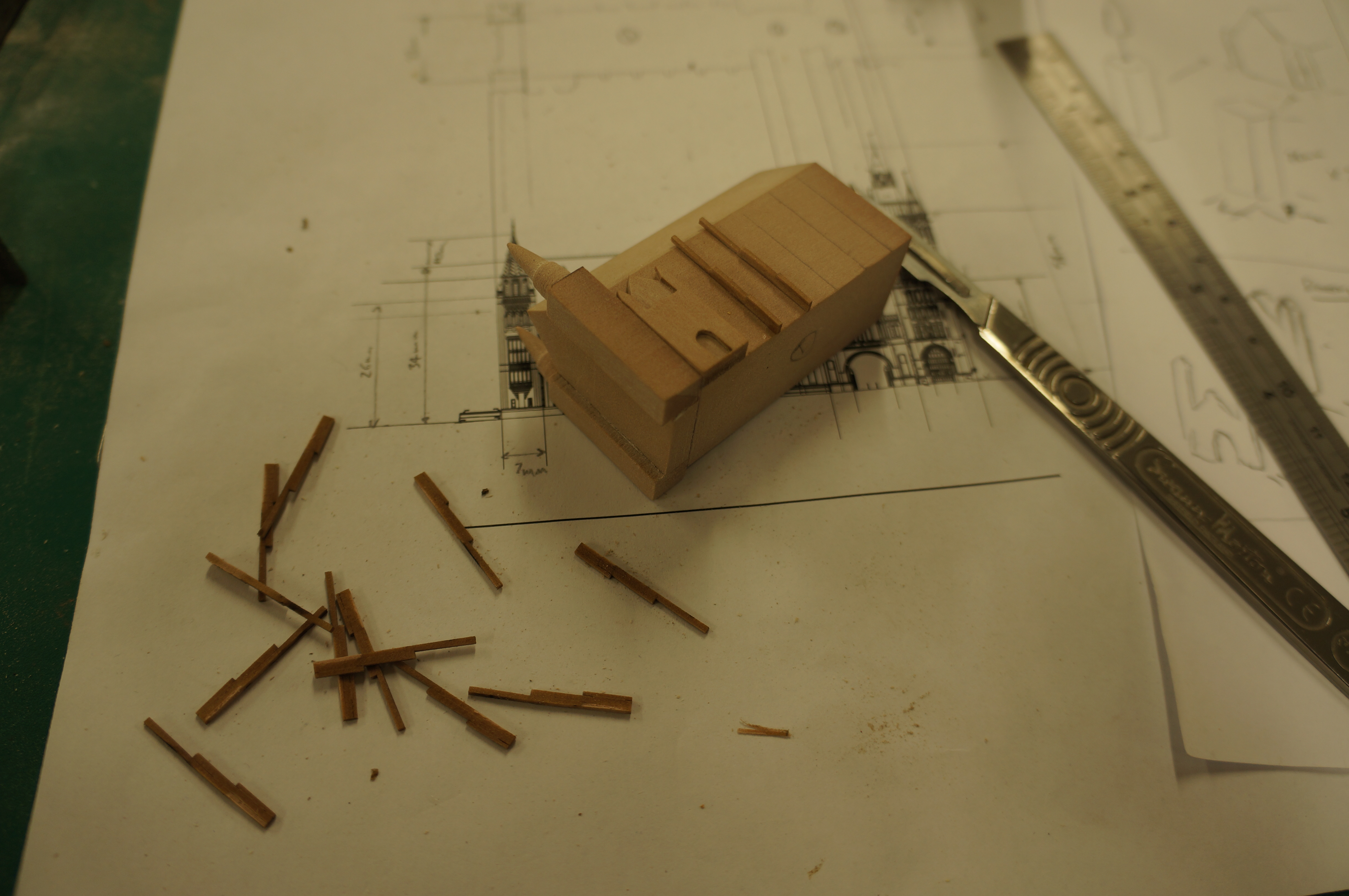 Finally I simplified the corner spires that finish the tower using the CAD Files maintaining the same basic level of detail as shown on the other detail elements. These were then fixed in place before fixing the tower to the archway and Whitworth Hall sections.
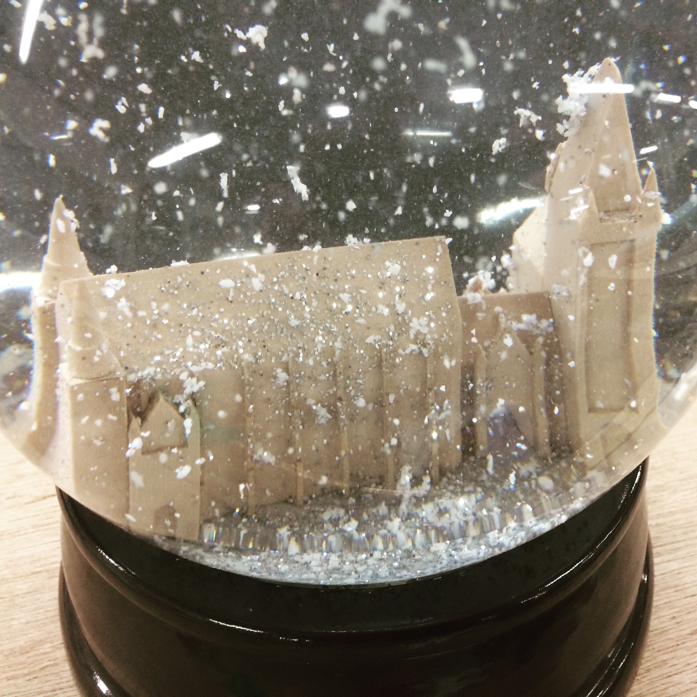
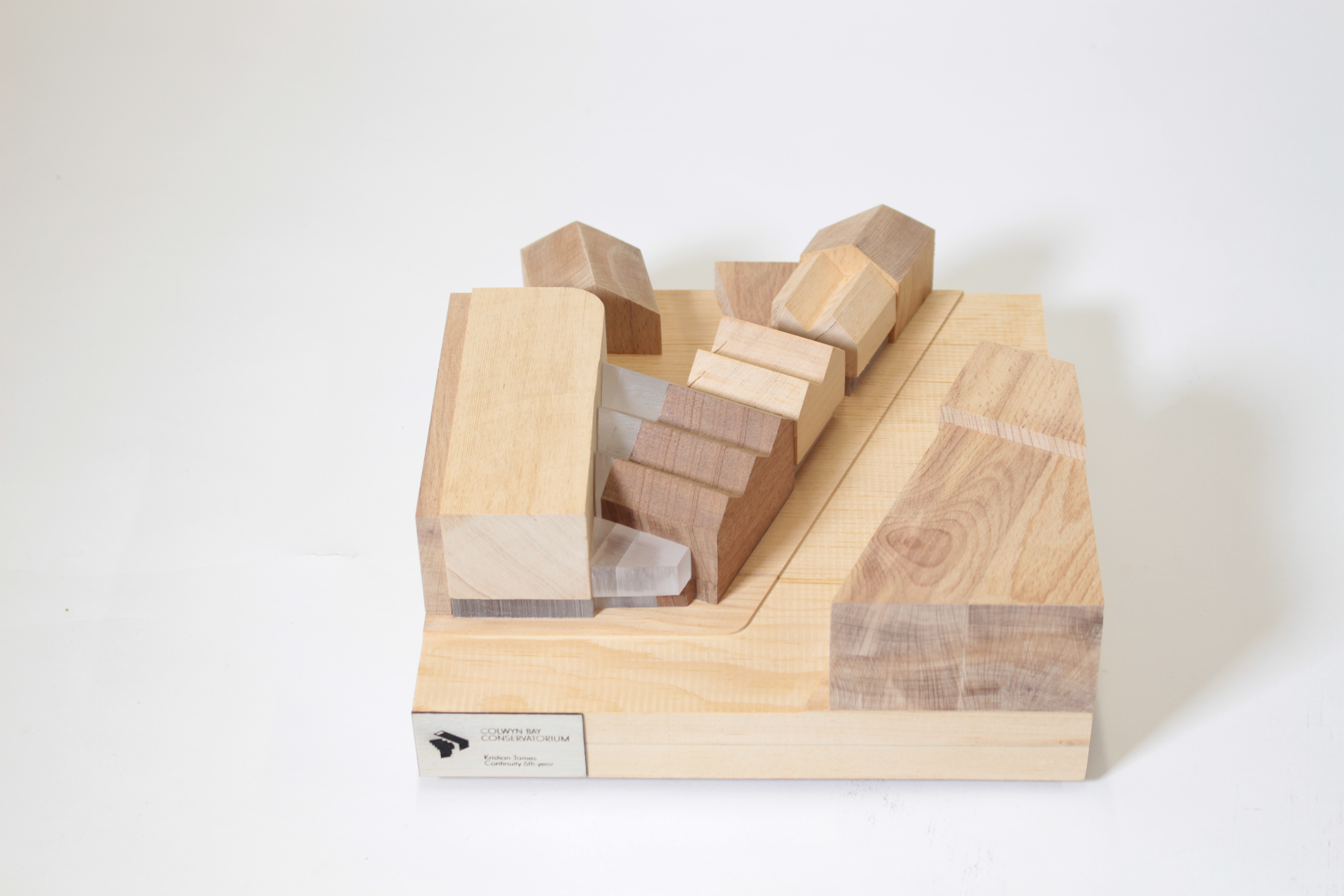
 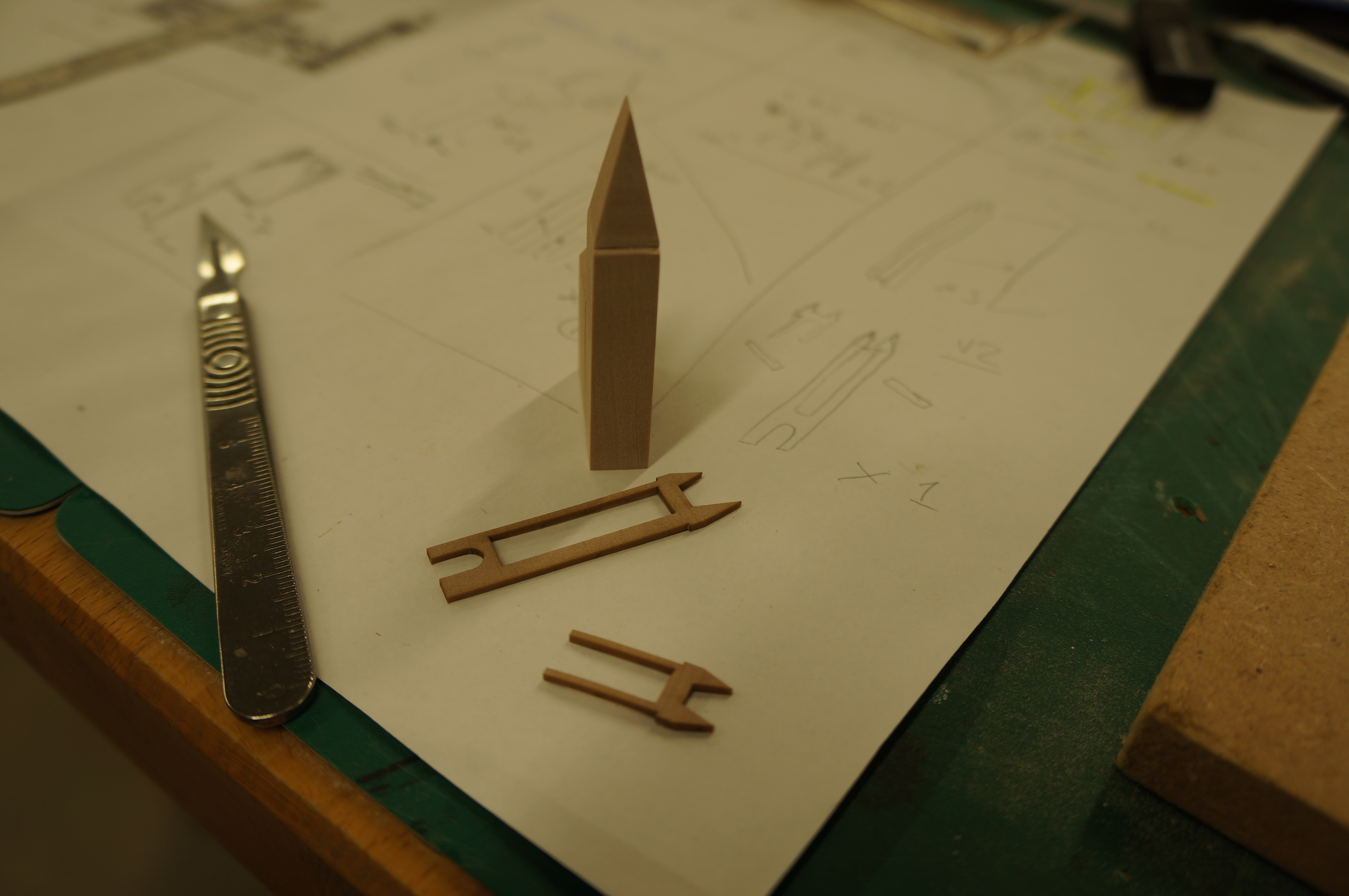 The model could now be painted easily due to the smooth surface finish of the components. In this case the raw material finish sufficed and it remains its clean colour.
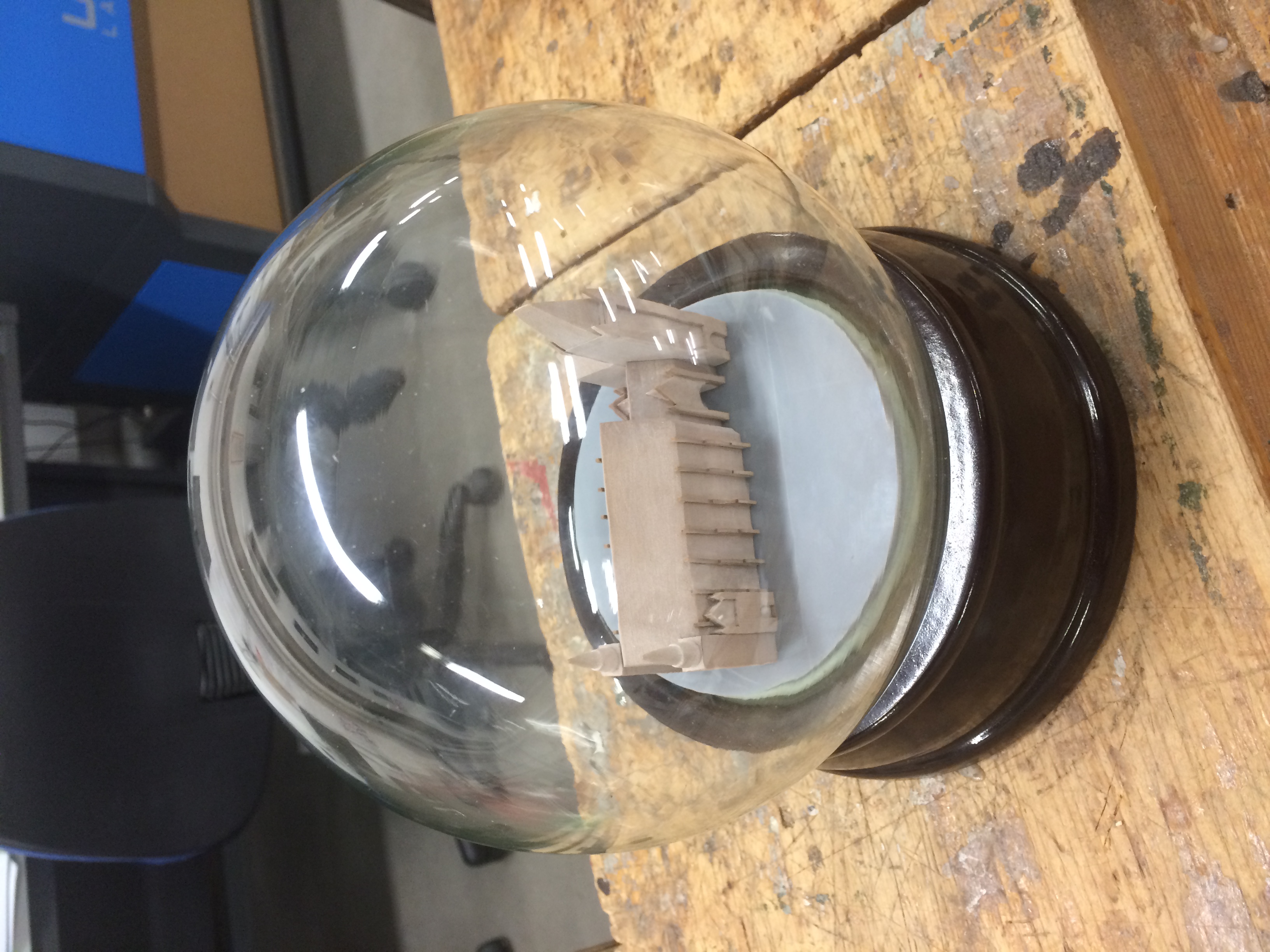
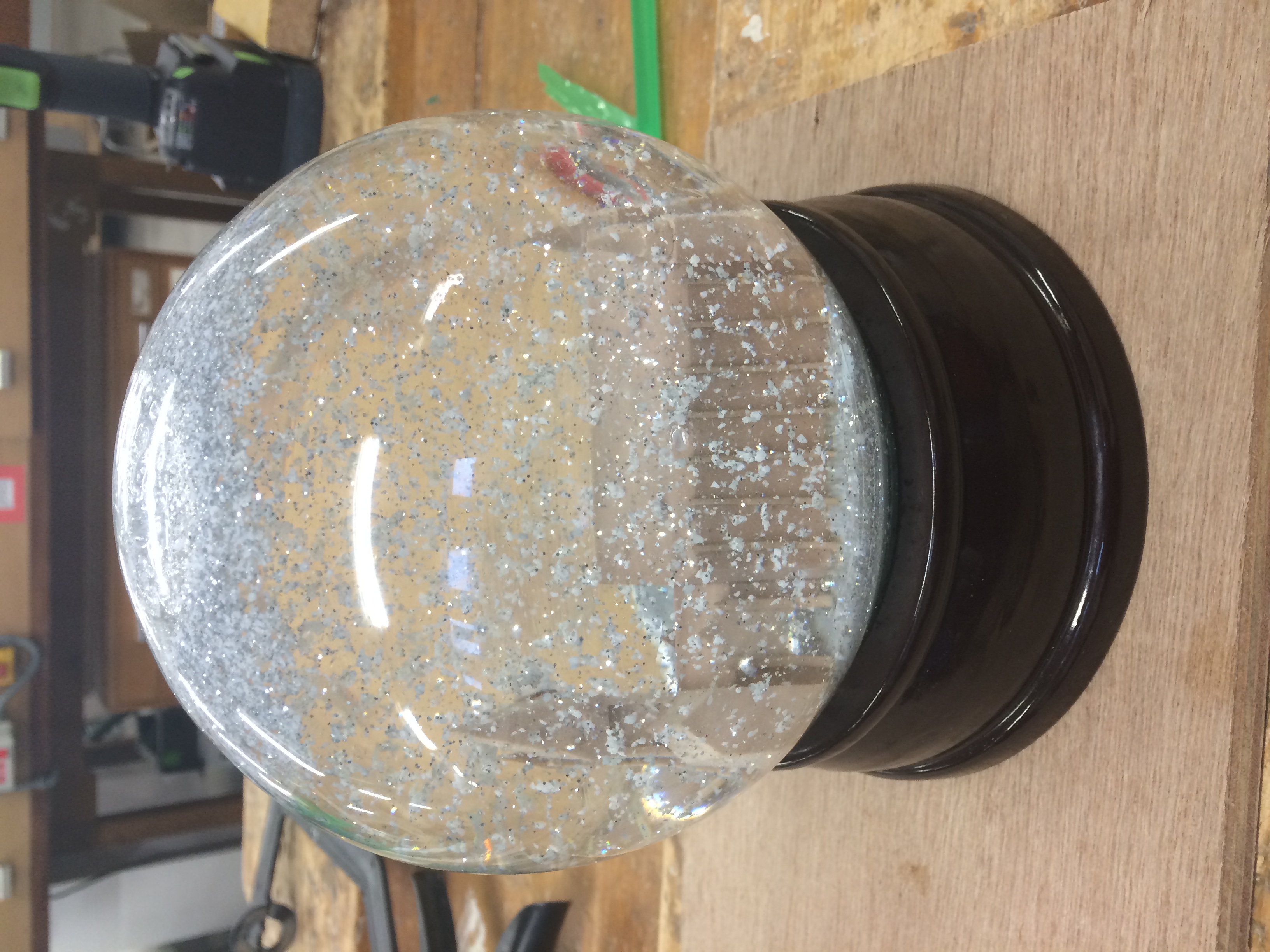
 The completed Model was then fixed into a snow globe to be used for University of Manchester marketing.
Hopefully this guide will give some useful pointers for your future models. If there’s anything you are uncertain about doing yourself always ask. – Scott