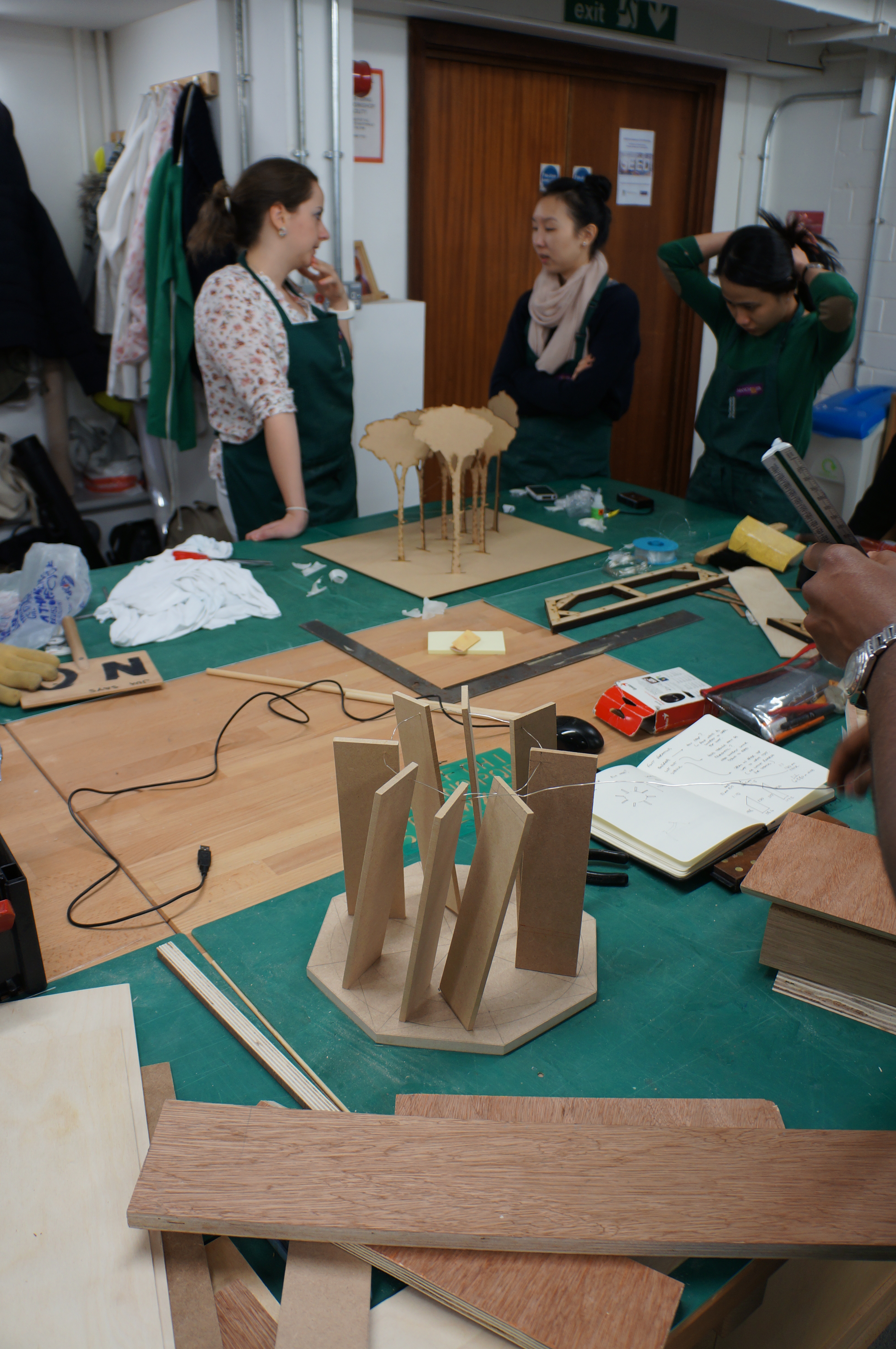
This project consists of 8 ‘peaks’ which each point toward a significant battle of the first world war. Each peak will feature poetry written by patients at who stayed at Dunham Massey during its use as a hospital for wounded soldiers coming back from the front.  As with the other ongoing pavilion projects, this concept began in physical form as a sketch model.Â
As with the other ongoing pavilion projects, this concept began in physical form as a sketch model. 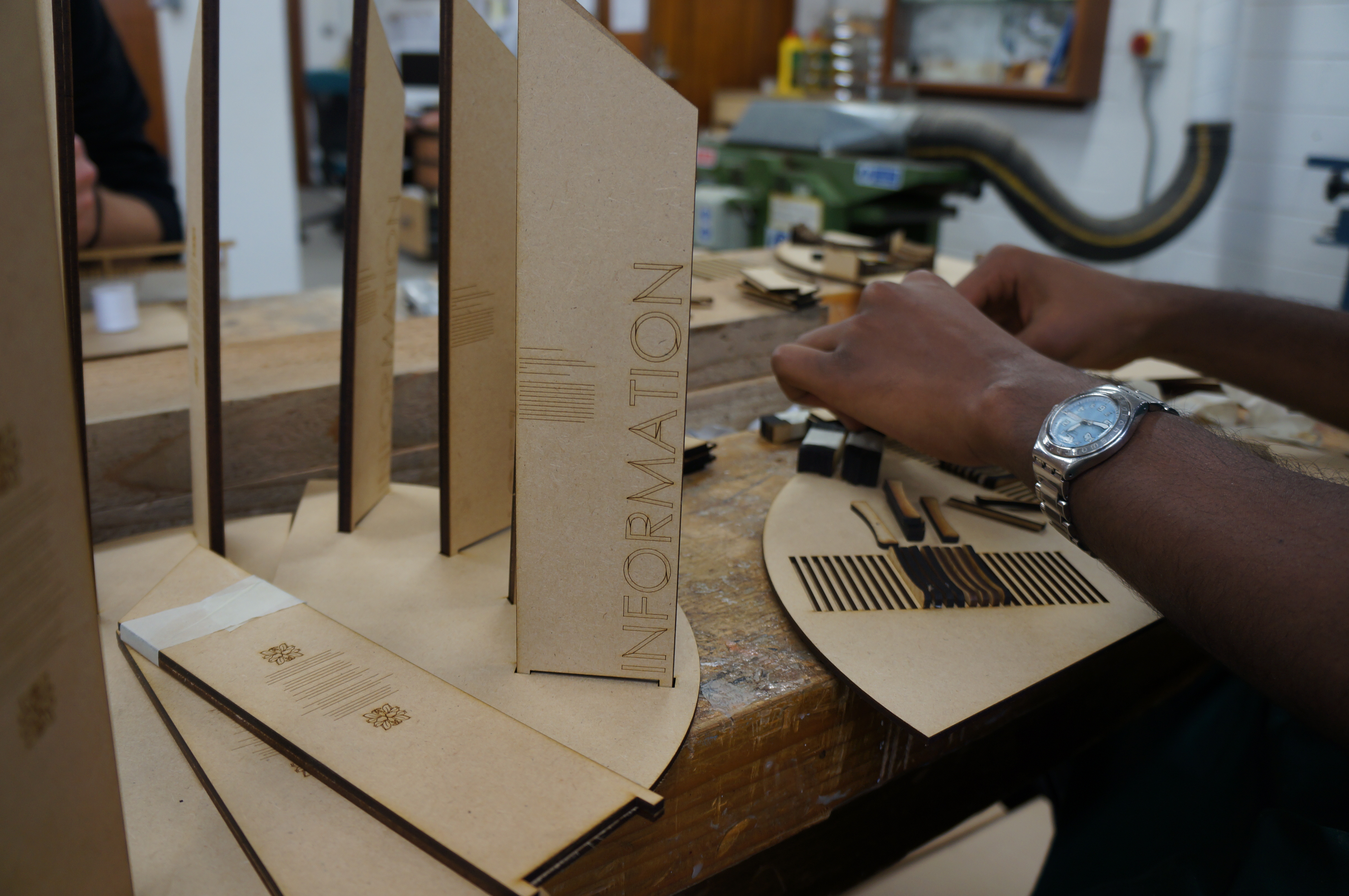
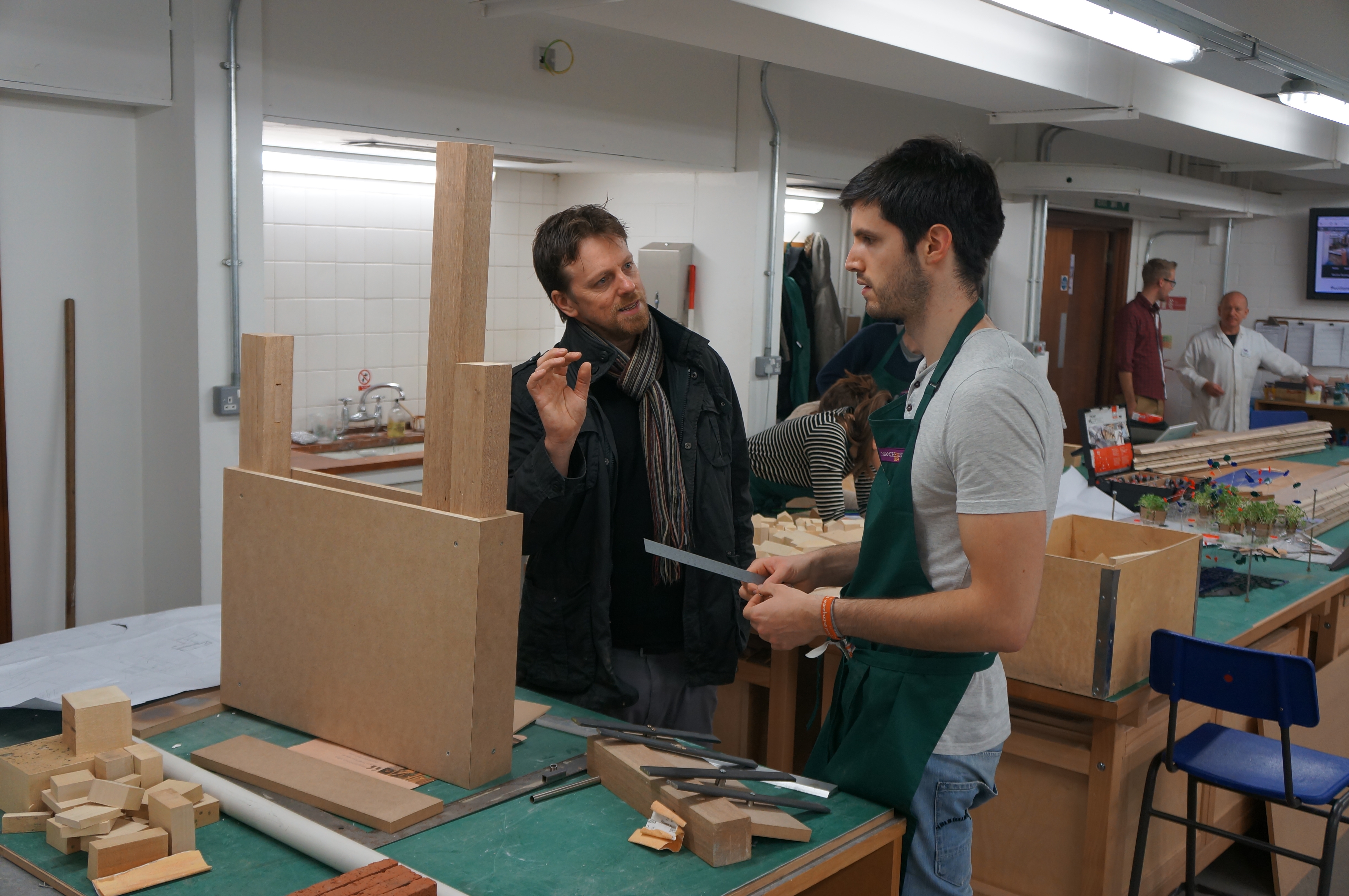
 Structural details were designed and refined through a series of test models. This example shows the internal frame construction to support each pillar in the circle.
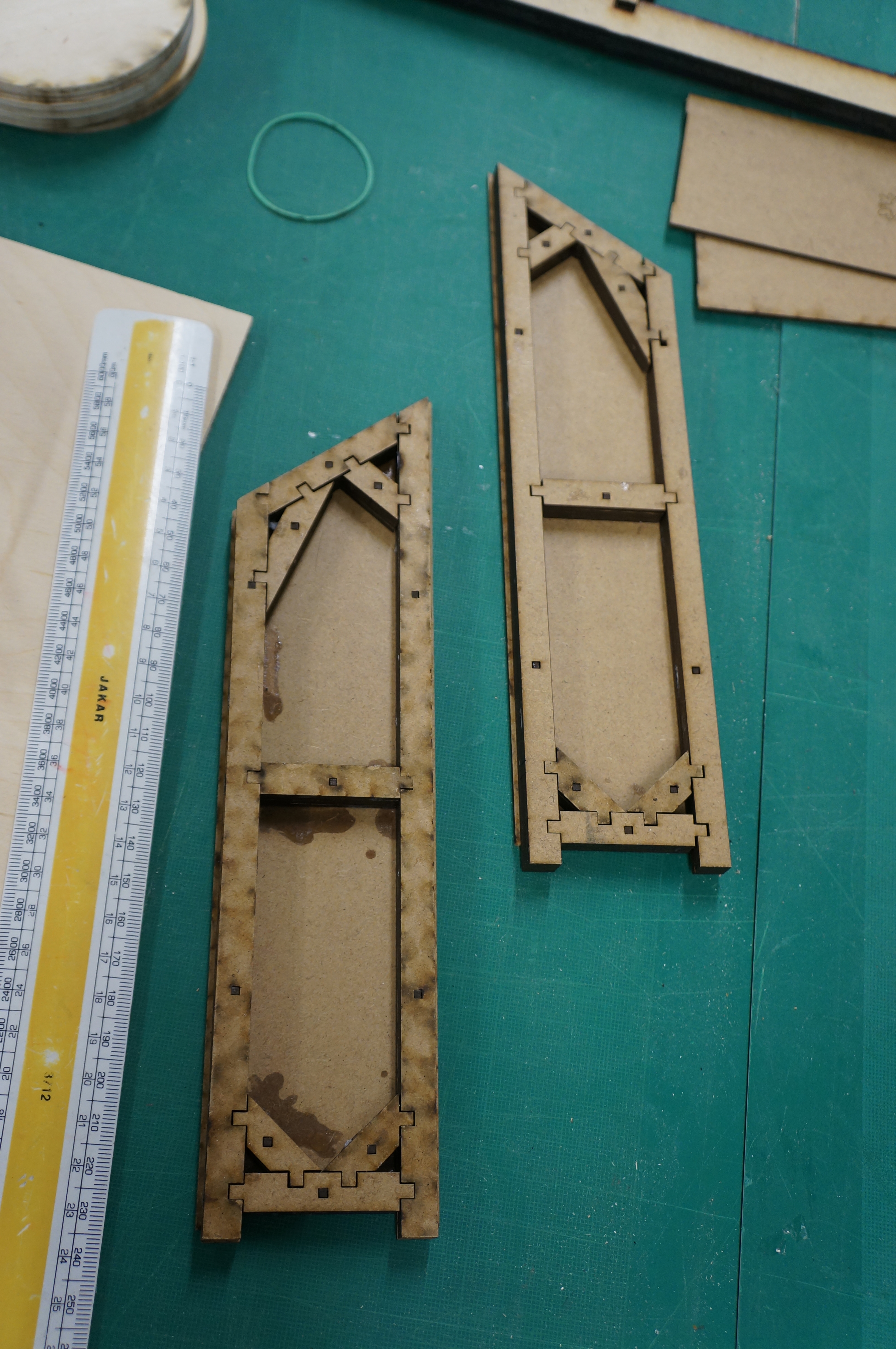
After test models were made at small scale the group went on to make some details at 1:1 to test assembly and strength in reality. This section below shows how the framework inside each panel would be fixed. These kind of 1:1 details are great design theory tests and offer as close an insight as possible to the finished look without building the full structure.
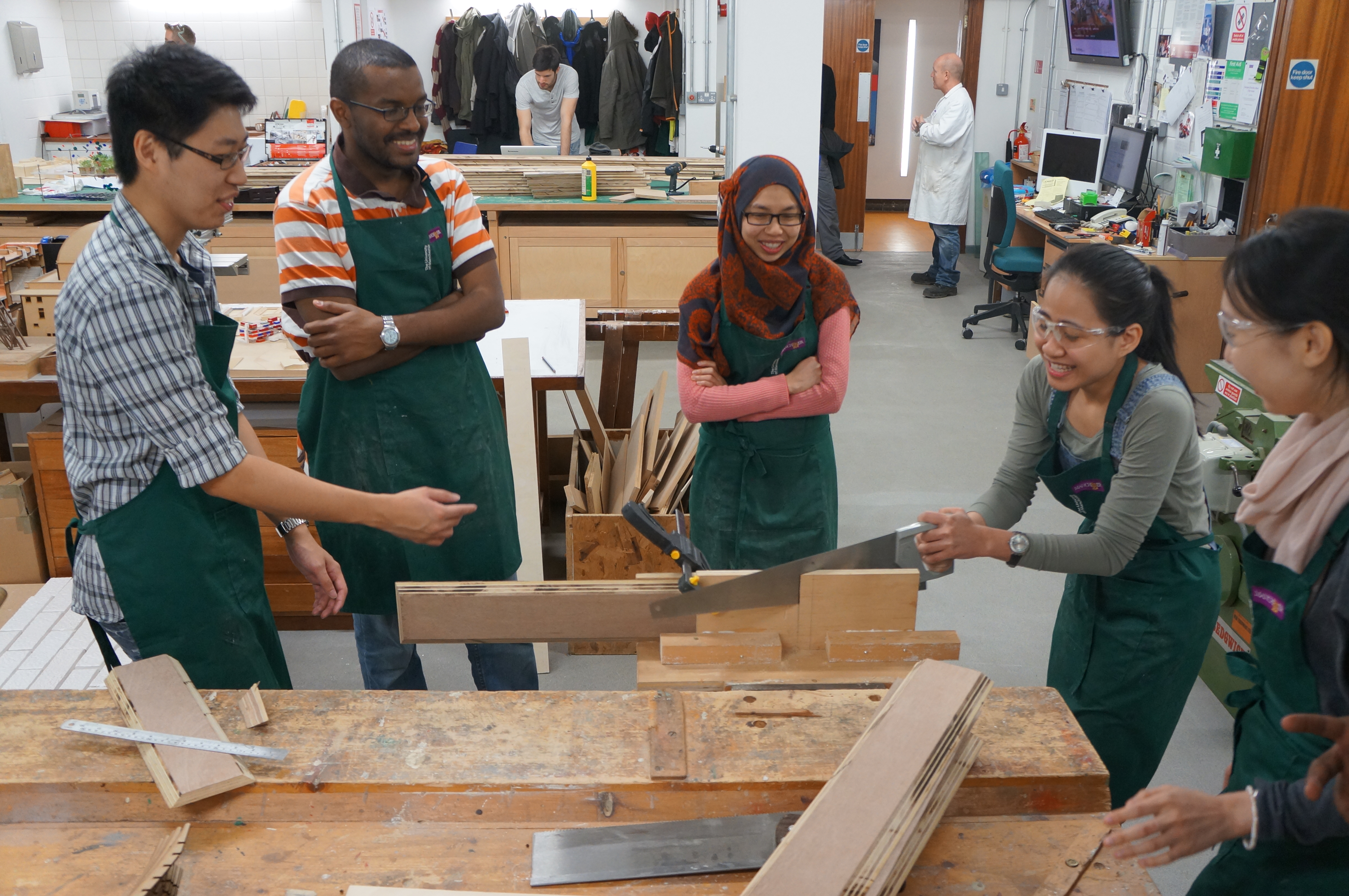
 Making components for this project, much like the concrete mould construction on one of the other pavilions required the mass production of specifically angled cuts using our circular saw.
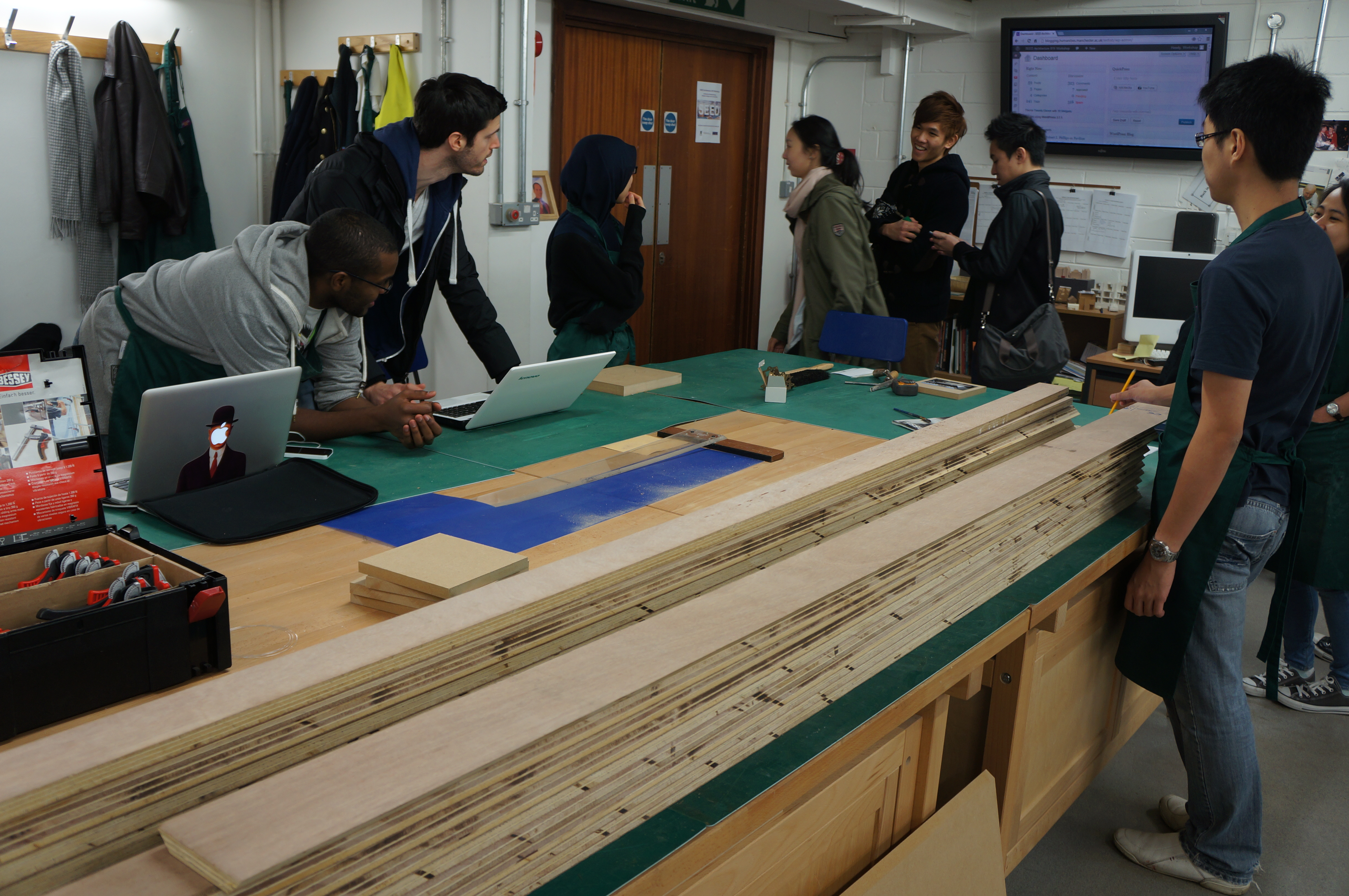
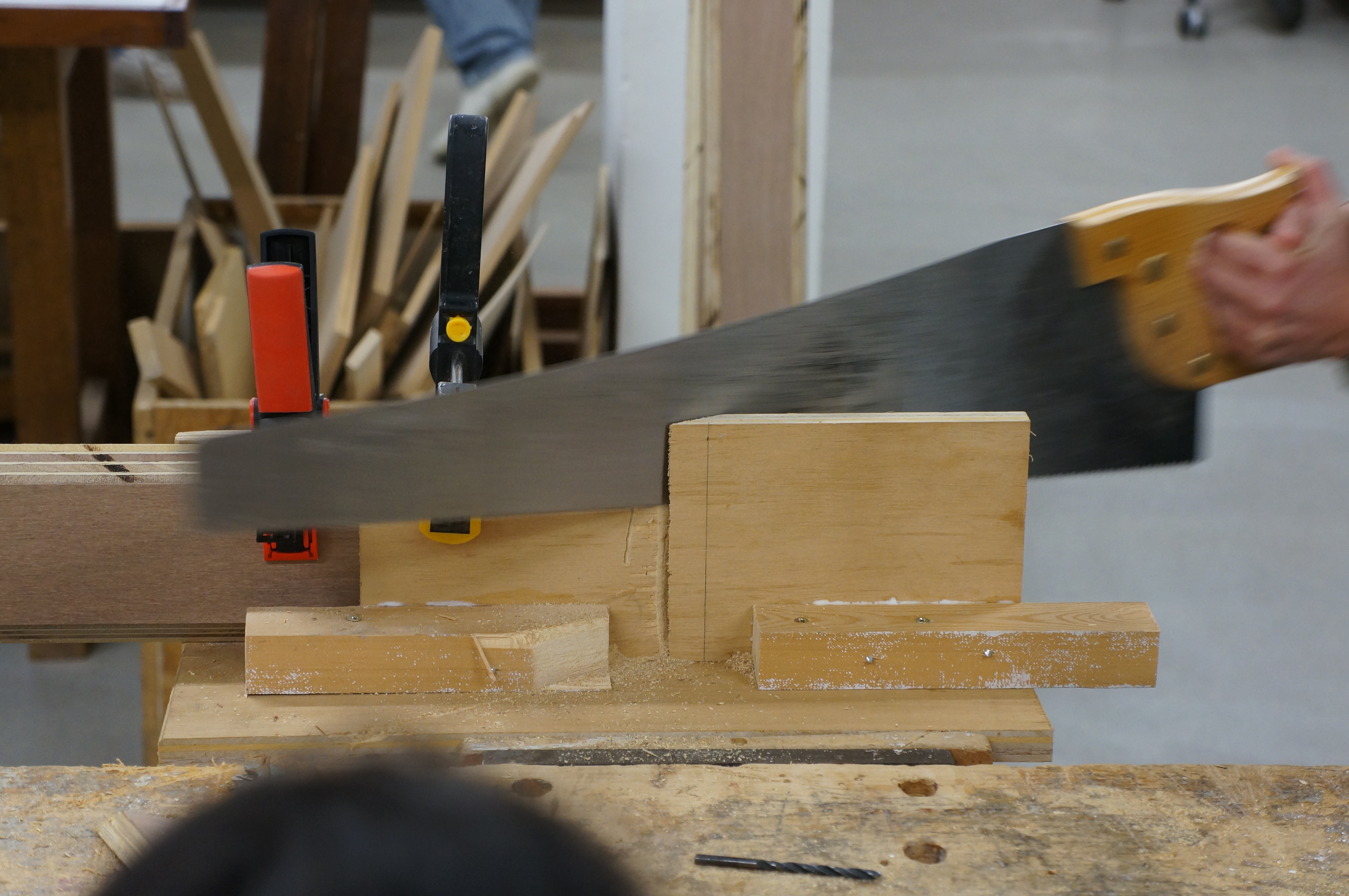
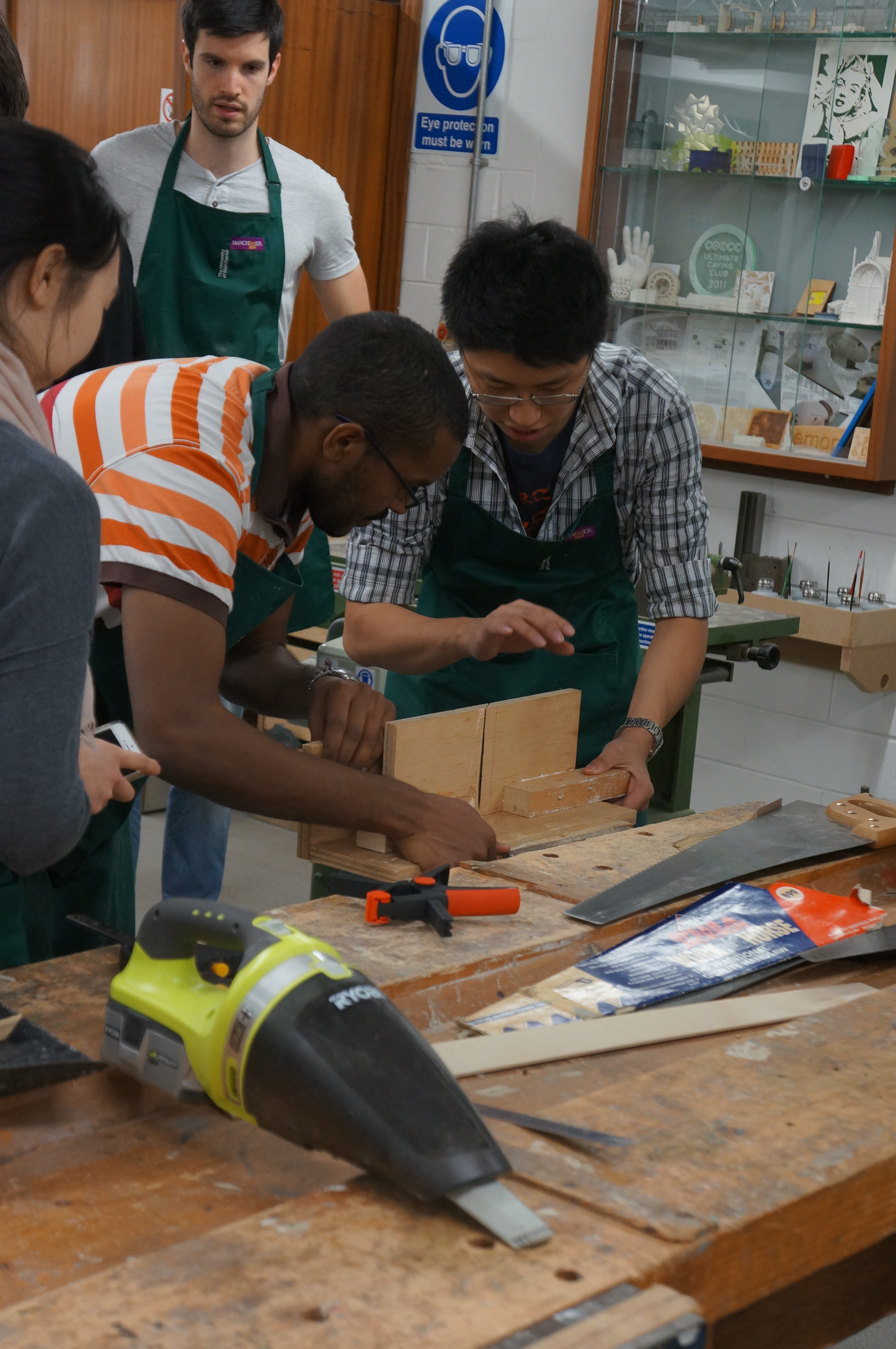 Due to the acute angle required for the top ends of each piece we were unable to cut the required angle using machines. In order to achieve the correct angle the group used a custom made mitre jig and hand saw to cut the correct angle at the end of each component. This proved to be a hand saw learning curve for most of the group after falling into the common misconception about using a hand saw – small fast movements will reduce the effectiveness of your cutting. Taking time to get used to using the main length of the saws teeth and allowing the saw to do the hard work always proves much more effective and less exhausting!Â
 The panels for each peak will be assembled using screws into pre-drilled holes (below) which will be plugged to make them less obvious.Â
The panels for each peak will be assembled using screws into pre-drilled holes (below) which will be plugged to make them less obvious. 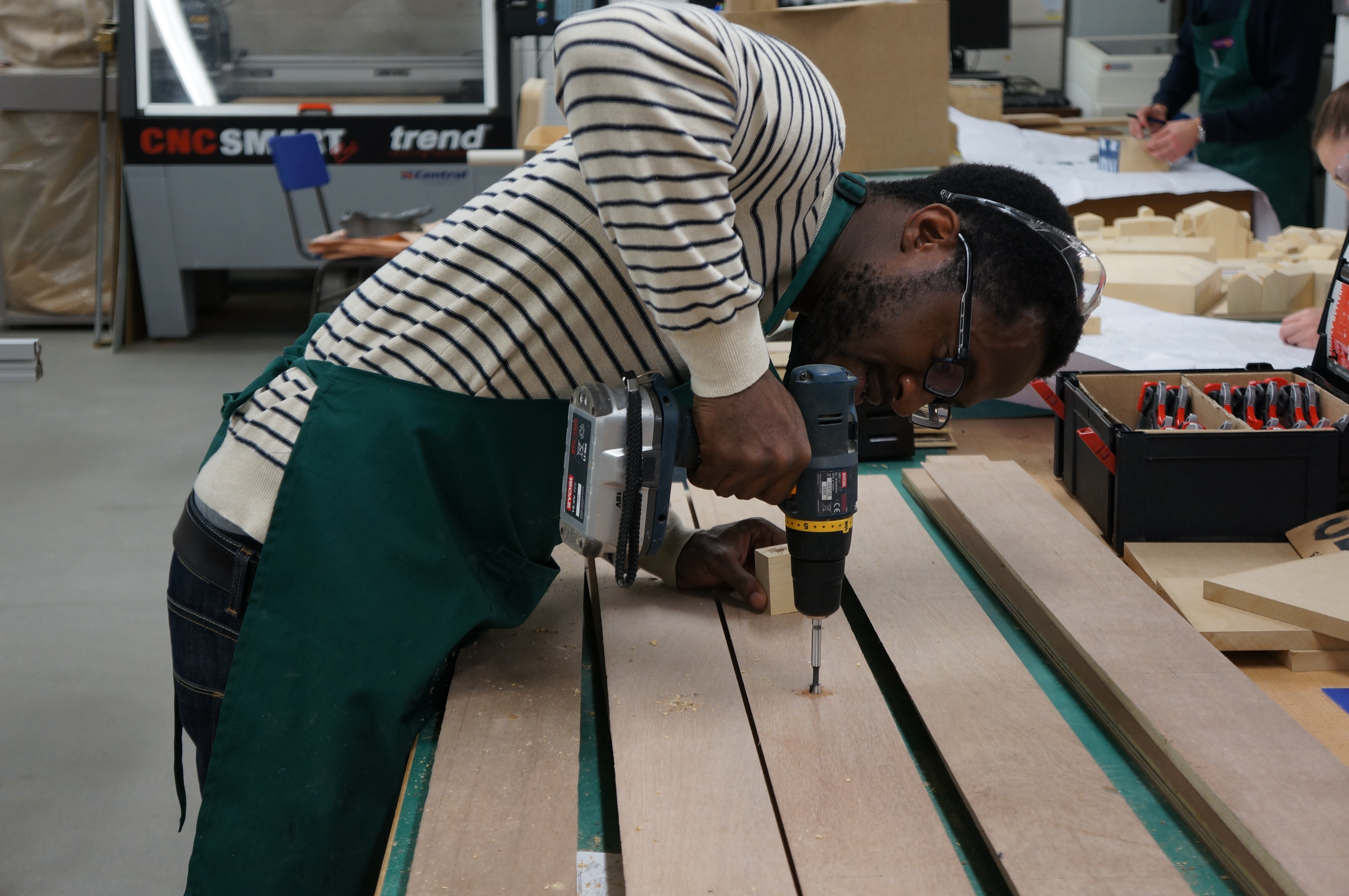 The main panels of each peak will be cut using a large CNC bed at FAB LAB Manchester. As with the other pavilion project developments, we will keep you up to date as things progress.
 Last week 2nd year students were given the task of further refining their designs for structural elements. By taking their initial ideas to the next stage they came up against many more problems to solve in particular how joining replicated components would work in practice as they made seven identical units to work with one another towards supporting a structure or forming a building form.Â
Last week 2nd year students were given the task of further refining their designs for structural elements. By taking their initial ideas to the next stage they came up against many more problems to solve in particular how joining replicated components would work in practice as they made seven identical units to work with one another towards supporting a structure or forming a building form. 


 Marco Wan had an interesting approach to creating the curved planes for his design. This process is called ‘glulam’ and as the name hints at, involves laminating sheets together with layers of glue and material whilst clamped in a given shape. This produced a very strong formed shape that can and is used for many 1:1 building applications. Very nice to see a student employing this technique in their model development.


